 Charlie Smith
The progress up to the end of the previous log is that I have two functioning radio boards and quite likely a functioning RF switch board. The next step being to actually measure in phase and quadrature (IQ) data. In the Nordic SDK, this is done by setting several registers on the radio peripheral to configure automatic constant tone extension (CTE) whenever a packet is sent, and then take IQ samples during the CTE of a packet being received. The IQ samples are then placed into memory to be processed with the MUSIC algorithm (or anything else).
Transmitter
So fist step is the code to transmit data. Most radio settings are the same as what are needed to transfer data normally. For now I don't actually care about the data being sent in each packet (but this could later be some sort of telemetry or similar). As such I can reuse my radio test code, based on the radio test from the Nordic SDK. I did modify this slightly to work with by board, as well as adding my USB logging backend. We then have to set two registers to enable CTE.
#define RADIO_DFEMODE RADIO_DFEMODE_DFEOPMODE_AoA
#define RADIO_DFECTRL1_NUM_REPEATS 0
#define RADIO_DFECTRL1_NUMBEROF8US (3 + (2 * (RADIO_DFECTRL1_NUM_REPEATS + 1)))
#define RADIO_DFECTRL1 ((RADIO_DFECTRL1_NUMBEROF8US_Msk & (RADIO_DFECTRL1_NUMBEROF8US << RADIO_DFECTRL1_NUMBEROF8US_Pos))    \
                        | (RADIO_DFECTRL1_DFEINEXTENSION_CRC << RADIO_DFECTRL1_DFEINEXTENSION_Pos))


NRF_RADIO->DFEMODE = RADIO_DFEMODE;
NRF_RADIO->DFECTRL1 = RADIO_DFECTRL1;
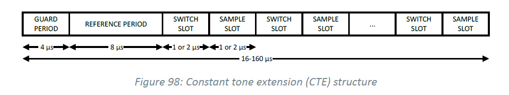 So for 1μs slots for each of the 8 antennas, the total time should be 12μs plus 16μs for each repeat of the antennas (although there is probably no need for doing multiple repeats, using the longer sampling slots is more useful). The formula given then gives the number of intervals with a 12μs headroom to make sure all sampling finishes before the CTE ends (this headroom can probably be reduced with testing).
 Receiver
The next step is setting up the receiver. This has several extra values to set. Firstly the RF switch control pins need to be setup. These will automatically be taken control of by the radio when needed (so shouldn't be used for anything other than the RF switch). The first step is to assign which pins are to be used. How many of these are set will depend on the array and RF switches being used, but can be any GPIO pins (I have seen some claims that they need to be high-drive only but this doesn't seem to be the case, at least not for my switching chips), do note that these should be set as outputs first using nrf_gpio_cfg_output.
NRF_RADIO->PSEL.DFEGPIO[0] = PIN_A;
NRF_RADIO->PSEL.DFEGPIO[1] = PIN_B;
NRF_RADIO->PSEL.DFEGPIO[2] = PIN_C;
Next the switching pattern needs to be set, this is done by clearing the pattern register, and then setting the default antenna to use, followed by the reference antenna and then each of the antennas to sample from. Generally the default and reference antenna will be the same, and then each antenna will be sampled in turn. If the RF switches being used switch too slowly (take longer than 2μs) you can add each antenna twice, then only use samples from every other slot.
// Clear the current pattern
NRF_RADIO->CLEARPATTERN = 1;

// Normal antenna to use
NRF_RADIO->SWITCHPATTERN = 0;

// Reference antenna
NRF_RADIO->SWITCHPATTERN = 0;

// The remaining antenna
for (uint8_t i = 0; i < 8; i++) NRF_RADIO->SWITCHPATTERN = (uint32_t)i;
Finally we need to setup the radio configuration registers. There is quite a bit more to set, and some of these settings may not be needed, but should be included. Firstly we need to set a pointer in memory for where to store IQ samples, this can be done with DFEPACKET. Setting the array location to DFEPACKET.PTR and max size to DFEPACKET.MAXCNT. We will then be able to use DFEPACKET.AMOUNT to check how many samples have been taken. Next we again need to set the DFEMODE to be AoA. For this example we know the DFE settings on both the receiver and transmitter, as such we can disable reading this data from the packet by setting the CTEINLINECONF register. Lastly we again need to set the DFECTRL1 register. This has the same settings as before (make sure that the CTE length matches that of the transmitter), as well as extra settings for how to take samples.
- SAMPLETYPE: Either IQ or MagPhase depending on how the data should be given in memory.
- TSWITCHSPACING: Either 2μs or 4μs depending on the if 1μs or 2μs slot sizes are being used. To avoid confusion, this is the total length of a switching slot and sampling slot rather than just the size of a slot.
- TSAMPLESPACINGREF: How often to take IQ samples during the reference period.
- TSAMPLESPACING: How often to take IQ samples during a sampling slot. Generally this should be as fast as possible.
- REPEATPATTERN: How many times to take a repeat of all sampling slots. Generally longer sampling slots is better, but this may still be useful depending on the antenna array being used.
- AGCBACKOFFGAIN: How much to reduce the amplifier gain when taking IQ samples. Likely to be fine kept at 0, but may be useful if some antennas have a much stronger signal than others. It may also help reduce noise but this is untested.
#define RADIO_DFEMODE RADIO_DFEMODE_DFEOPMODE_AoA
#define RADIO_CTEINLINECONF ((RADIO_CTEINLINECONF_CTEINLINECTRLEN_Disabled << RADIO_CTEINLINECONF_CTEINLINECTRLEN_Pos)  \
                            | (RADIO_CTEINLINECONF_CTEINFOINS1_NotInS1 << RADIO_CTEINLINECONF_CTEINFOINS1_Pos)          \
                            | (RADIO_CTEINLINECONF_CTEERRORHANDLING_Yes << RADIO_CTEINLINECONF_CTEERRORHANDLING_Pos)    \
                            | (RADIO_CTEINLINECONF_CTETIMEVALIDRANGE_20 << RADIO_CTEINLINECONF_CTETIMEVALIDRANGE_Pos))

#define RADIO_DFECTRL1_NUM_REPEATS 0
#define RADIO_DFECTRL1_NUMBEROF8US (3 + (2 * (RADIO_DFECTRL1_NUM_REPEATS + 1)))
#define RADIO_DFECTRL1_AGCBACKOFFGAIN 0
#define RADIO_DFECTRL1 ((RADIO_DFECTRL1_NUMBEROF8US_Msk & (RADIO_DFECTRL1_NUMBEROF8US << RADIO_DFECTRL1_NUMBEROF8US_Pos))      \
                | (RADIO_DFECTRL1_DFEINEXTENSION_CRC << RADIO_DFECTRL1_DFEINEXTENSION_Pos)                                     \
                | (RADIO_DFECTRL1_SAMPLETYPE_IQ << RADIO_DFECTRL1_SAMPLETYPE_Pos)                                              \
                | (RADIO_DFECTRL1_TSWITCHSPACING_2us << RADIO_DFECTRL1_TSWITCHSPACING_Pos)                                     \
                | (RADIO_DFECTRL1_TSAMPLESPACINGREF_125ns << RADIO_DFECTRL1_TSAMPLESPACINGREF_Pos)                             \
                | (RADIO_DFECTRL1_TSAMPLESPACING_125ns << RADIO_DFECTRL1_TSAMPLESPACING_Pos)                                   \
                | (RADIO_DFECTRL1_REPEATPATTERN_Msk & (RADIO_DFECTRL1_NUM_REPEATS << RADIO_DFECTRL1_REPEATPATTERN_Pos))        \
                | (RADIO_DFECTRL1_AGCBACKOFFGAIN_Msk & (RADIO_DFECTRL1_AGCBACKOFFGAIN << RADIO_DFECTRL1_AGCBACKOFFGAIN_Pos)))

#define RADIO_DFEPACKET_MAXCNT 512
static uint32_t dfePacket[RADIO_DFEPACKET_MAXCNT];

// Setup the packet to retrieve IQ data
NRF_RADIO->DFEPACKET.PTR = (uint32_t)dfePacket;
NRF_RADIO->DFEPACKET.MAXCNT = RADIO_DFEPACKET_MAXCNT;

// Enable recieving data to calculate AoA
NRF_RADIO->DFEMODE = RADIO_DFEMODE;
NRF_RADIO->CTEINLINECONF = RADIO_CTEINLINECONF;
NRF_RADIO->DFECTRL1 = RADIO_DFECTRL1;
With these settings I should expect 64 samples in the reference period, followed by 8 sample from each antenna. However we actually get samples from the switching periods as well, for a total of 16 samples per antenna. What is more, the radio seems to make repeats of all the antennas for the full length of the CTE period, even when set to not make any repeats (I can't see why it should do this, but it doesn't really matter). This can be seen for looking at the RF switch control pins (note I have changed the reference antenna to make it clear were the CTE starts):
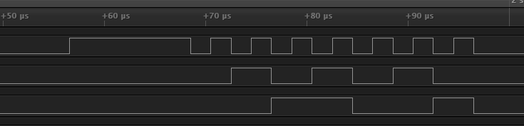
This shows a 12μs use of the reference antenna (guard plus reference slot) followed by 14 combined switching and sampling slots lasting 2μs, giving a total 40μs. Which is the total length of the CTE as configured for no repeats (we can reduce the extra sampling by only using a 32μs CTE, but this still gives 32 extra samples). This means we end up with a total of 288 IQ samples. While this is more than it should be, we can just ignore the extra samples, with the only downside being it takes slightly longer to collect samples.
Pitfalls
As usual, it wasn't all smooth sailing getting the IQ sampling working correctly. So I would like to include some of the main issues I ran into.
Logging floats
For some reason Nordic SDK needs you to treat floating point values differently than anything else when formatting them in a log. When logging you will likely use something like this:
NRF_LOG_INFO ("Here is a uint %u", someUINT);
However, for a float you have to instead use:
NRF_LOG_INFO ("Here is a float " NRF_LOG_FLOAT_MARKER, NRF_LOG_FLOAT(someFloat));
While this doesn't really matter, it does make it become confusing if you want to include multiple values. The Nordic SDK only supports up to 6 arguments when formatting, and while this might not seem a problem in the two examples above, the issue is that NRF_LOG_FLOAT_MARKER and NRF_LOG_FLOAT have the following definition:
#define LOG_FLOAT_MARKER "%s%d.%02d"
#define NRF_LOG_FLOAT(val) (uint32_t)(((val) < 0 && (val) > -1.0) ? "-" : ""),   \
                           (int32_t)(val),                                       \
                           (int32_t)((((val) > 0) ? (val) - (int32_t)(val)       \
                                                : (int32_t)(val) - (val))*100)
So rather than just being the single value you might expect, the float gets split into 3 values, so makes it much easier to run into the maximum argument limit. Of course this isn't exactly a problem either, as you can just make multiple log messages (although you may need to use NRF_LOG_RAW_INFO).
Radio Disabling
The second, and more problematic, issue I ran into relates to how the radio gets disabled after use. The initial problem was that I was getting far fewer samples than expected, corresponding to just the reference period plus a couple more. It seemed like a problem with the length of the CTE. In searching for some solution I found this post which as a very simple way to test if the CTE is enabled or not. After sending a packet you wait till the CTE should start, and then increment a counter as fast as possible until when the CTE should have ended using the following code:
uint32_t counter = 0;

while (NRF_RADIO->EVENTS_PHYEND == 0U)
{
       while (NRF_RADIO->EVENTS_END == 0U) {}
    counter++;
}

NRF_LOG_INFO ("The packet was sent, counter had value %u", counter);
Looking at the data sheet for when events trigger we can see that the END event triggers after CRC and before CTE, while the PHYEND event triggers after CTE:
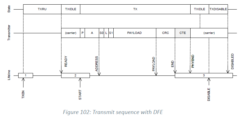
If the CTE is enabled we should expect the counter to have a larger value for a longer CTE, while the counter should be very small when there is no CTE enabled (not quite zero as in practice there will be a short time between the two events being set). This also shows us the problem we are having. While this test showed that the the CTE was enabled, the issue is that in the radio test example the receiver and transmitter both wait till the END event before disabling the radio. But clearly this is before the CTE has finished so the radio will be disabled before all samples have been collected. The fix is to wait till the PHYEND event before disabling the radio (somehow I managed to realise this was the fix for the receiver and then spend a day or so wondering why all the samples taken after the reference period had a much smaller amplitude, almost like the transmitter was also being disabled too early).
Processing
With that we now have IQ samples being taken (if you want a good explanation of IQ sampling is, I found this as quite a good article) now all that needs doing is to put the data into the MUSIC algorithm which we already have working and the project should be almost complete... right. Well spoilers, no its not that simple. But first lets look at some of the data we now have.
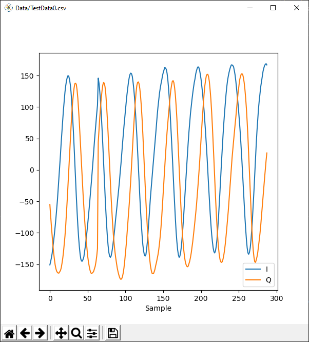
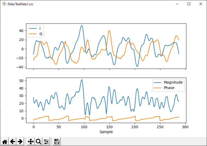
Doesn't look quite as good does it. That's partly because I have chosen one of the worst examples but it highlights what the probably issue is. It looks like there are multiple copies of the wave, overlaid with each other. This would point to there being reflections of the signal within the radio switch board. Unfortunately I don't have a vector network analyser to find out (if anyone has any ideas about getting one I'm open to suggestions, but remember I am a student and can't afford anything expensive). There is also another issue with this data. I based my initial simulations on receiving IQ data for a 2.4GHz wave, and while that is the frequency being used it is not the frequency of the wave that the IQ data forms. Instead I should expect a 250kHz wave when using 1Mb/s. So lets look at a Fourier transformation of the data:
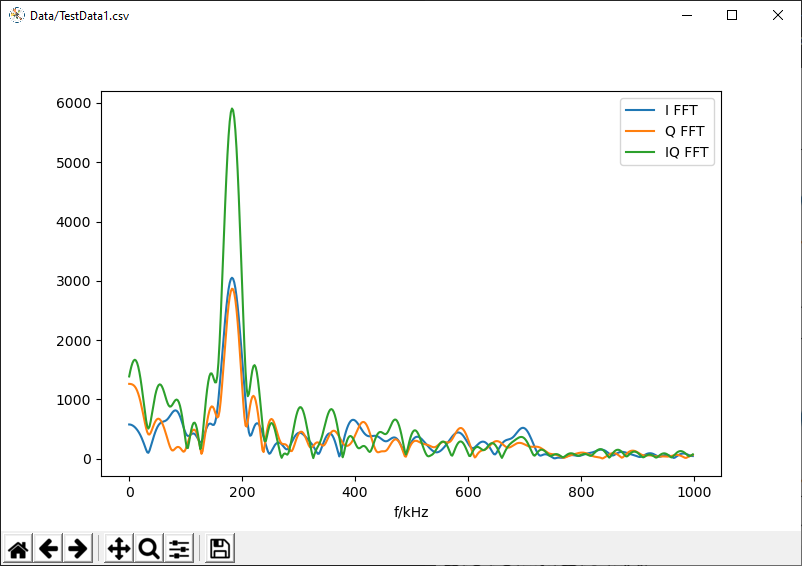
This has a peak about 182kHz. There is also a tiny peak at 250kHz, but it is insignificant in comparison. Now this could be that we are doing a Fourier transformation on data that has abrupt changes in phase but it still seems a slight issue. Ok, but does the MUSIC algorithm give anything useful:
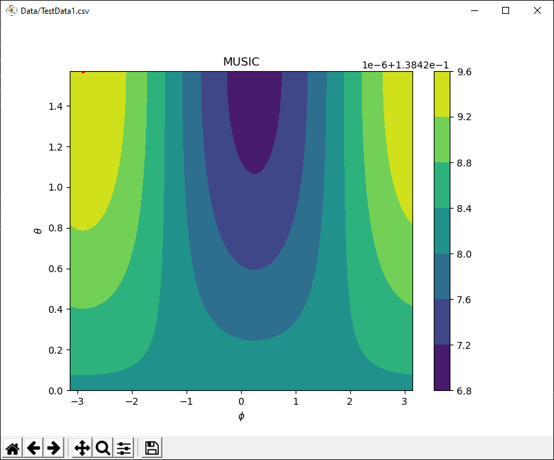
I think that will be a solid no. If we look back to the initial testing, be where getting a peak with a value of about 20, compared to the ground noise of pretty much 0. Also, when doing this test the transmitter was held at an angle which should give a value of θ of about π/2 not π. So perhaps we need to go back to our simulation.
Simulation Time Again
So with the new knowledge that we are using a 250kHz wave lets look at what we should expect from the MUSIC spectrum:
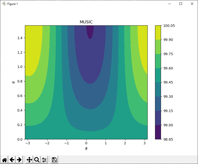
This seems to have a very similar shape to the actual data, but with peaks about 100 times larger. Lets also rerun our simulation of projectile motion:
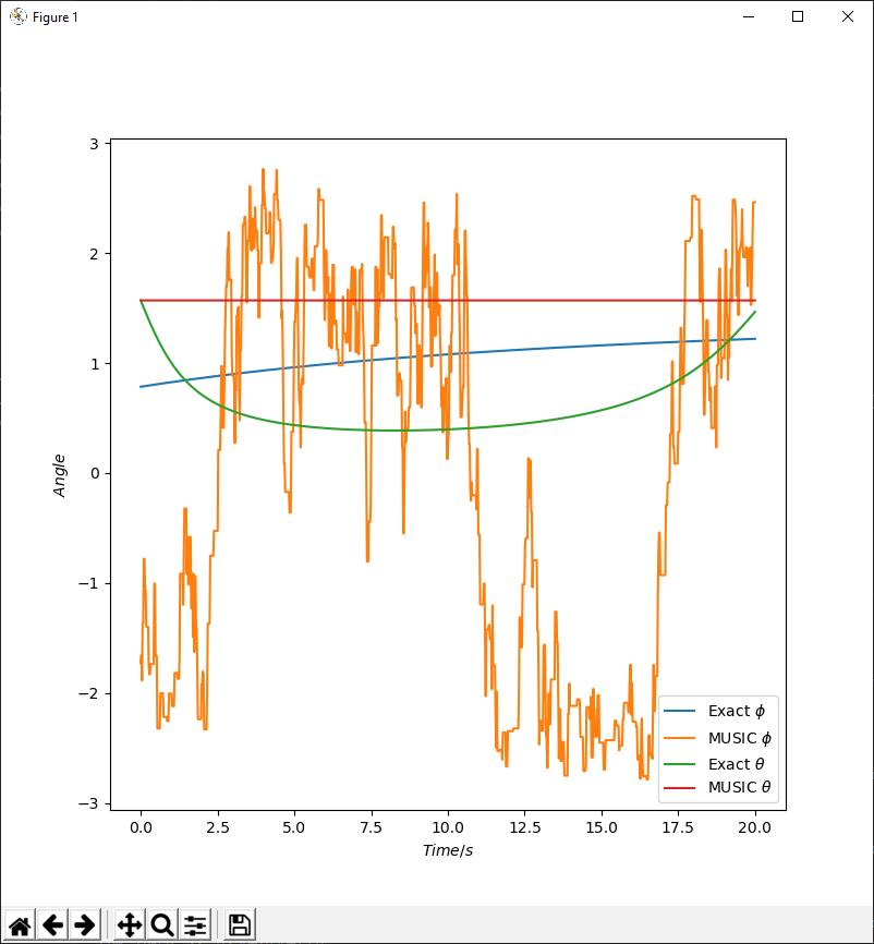
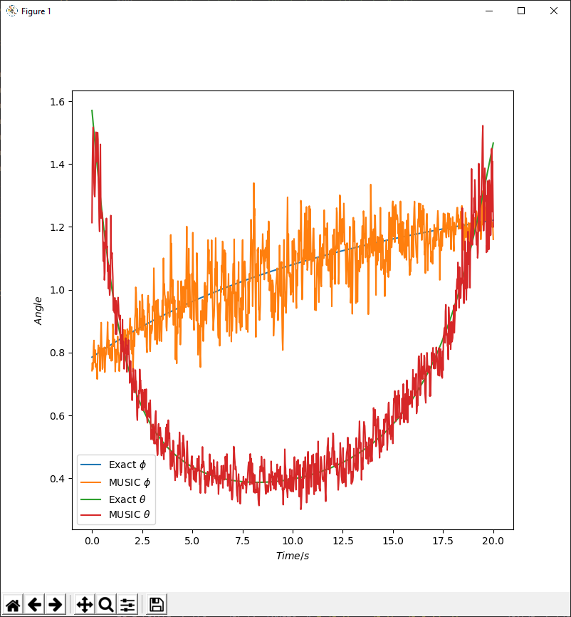
Well that doesn't look good. Firstly θ is stuck at π/2 as we saw in the real data, while φ fluctuates around. But what can I do to fix this. Well its a bit difficult to tell. It possible that a larger radius would improve things, but also if the issue is with reflections the noise will be far too great to do anything. From playing about with my simulation the a 0.1% phase noise corresponds well with the real data. Reducing this by a factor of 100 starts give give some useful results. In combination with a larger radius array (~10cm rather than 4.5cm) and the data is almost what we had before, although possible a more aggressive low pass filter will be needed.
So what is the future plan. Increasing the antenna radius is relatively simple (with a current limit of about 12cm) as I am not using PCB antennas, but I absolutely need to reduce the noise, without the proper equipment it will be rather difficult to work out the problem. For example another possible issue is that the coax cable between the radio and switch board may not be properly shielded and so act as an antenna in its own right. Its also possible that I can filter the IQ data before passing to MUSIC. But currently I am unsure about how to do that effectively. While taking more samples seems to have little effect in simulation. I could also redesign the switching board, but I don't know what about it needs to be changed so would probably run into the same issue.
Another thing that needs work on is real time processing of IQ data. Currently this is being done by in Python, but really I should be able to get it working on the device. In fact I do have it working on the device, but it needs a little more work so will leave that to the next project log.
So as it currently stands I will continue to try out things as I get ideas, and feel free to make suggestions, I have probably missed something important.
Also I am aware that the code looks a little odd, but C++ code snippets seem to have a mind of their own when it comes to highlighting.
Discussions
Become a Hackaday.io Member
Create an account to leave a comment. Already have an account? Log In.