 Paul McClay
edit: more pix + result
tl;dr: while writing this it occurred to me that the simple answer may be conventional instead of climb milling.
Subject to further testing, it appears that Dr. Vahid has rescued me from not ever figuring this out on my own. His own thesis work is out of scope, but his literature review called out clues that I doubt I would have found apart from the context in which he framed them. Thanks, Orang.
About wicked chatter when force is applied in the direction of motion...
Yup, that can be a problem. Especially when the lead screw is/has:
- self-locking [M3x0.5: yup]
- low rotational inertia vs load inertia [wimpy screws/hefty XY table]
- low axial compliance [low=fit for purpose; high=unsuitable]
Well, that pretty much means "this project". And that

does not encourage.
About axial compliance:
- This chatter thing went from marginal to major after intentionally reducing axial compliance
- The CH-SM1545 motors (probably all these little can-stack stepper + lead screw assemblies) have asymmetric axial compliance because they have a spring on the motor end pushing the rotor/screw into a fixed bearing at the other end. Reviewing cases where similar motion in one direction or its opposite provoked more or less chatter: more chatter has correlated with loading against the unsprung end.
This wasn't a thing that I really wanted to corroborate. Springing the unsprung end so that the screw floats between two springs might quell chatter in both directions, but that won't help with accurate or repeatable positioning. Instead I tried to do the opposite.
About self-locking:
The screw self-locks due to its shallow pitch at (d/6)/rev. The fine pitch multiplies the force & precision possible from the tiny motor relative to what something like #CDCNC could get from a similar motor driving a steeper pitch screw as in a CD/DVD or similar scavengeable device. So that's a given for this project.
[Hey - anybody know what sort of scavengeable stuff uses finer pitch stepper+screw assemblies?]
So how about rotational inertia of the screw?
It would be nice if we could hang flywheel off an end of the screw, which is probably not often said around stepper motors, but both ends are captive. Instead I tried this:
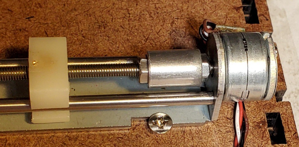
I really don't like how this eats up useful length of the screw.
Other side-effects that I really don't like include the screw jamming hard when it carries augmented rotational inertia to either end of travel. At least that gives evidence that it makes a difference. How much difference is necessary to shift the ratio of screw/load inertias from too small to safely less small? Dunno.
That randomly found piece is aluminum and smaller diameter than could potentially clear the ways. A couple of slightly larger diameter M3-threaded brass (or rhenium) disks jammed together would have the same or greater inertia in less length. But any metal part here adds to the BoM which I'd rather minimize. And I didn't find any really suitable standard part. Something like a pair of "DIN 467" nuts (that's a thing‽) but different. A best-fit part would be simple to turn on a lathe, but that departs further from the simple BoM intent.
But anyhow...
(edit: add pix + tweak text)
Adding "flywheels" to the X & Y screws seemed to work for calming the chatter out of, for one test case, the four quadrants of the initial facing cut around my test pattern and the beginning of the four walls of the pocket. That was somewhat encouraging but less than definitive because at the same time the Z axis was flaking out -- then flaked out.
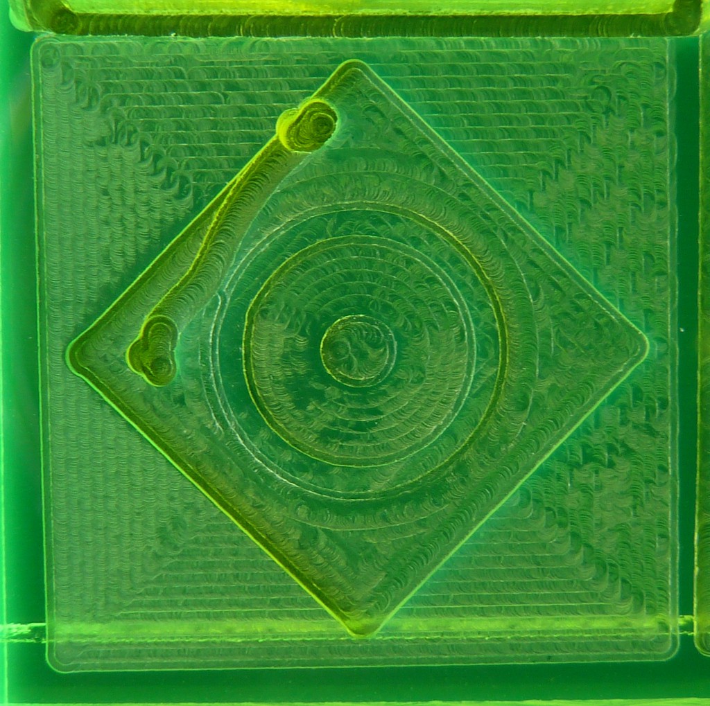
That test cut didn't get very far because the Z axis stopped lifting early in that job, so there isn't much to compare except the face cut and the first layers(?) of the square pocket. The sides of the pocket at least started straight. Some quadrants of the face cut had a slower/longer-period variation, but no chatter and no visible stutter to the X or Y motions.
On looking closer, that slower period variation was the Z axis floating up & down. Most dramatically on the right (decreasing Y). Apparently it's possible to balance that too well - or something. Unclear how that related to general failure of Z motion.

So maybe that added enough inertia to the screws, relative to inertia of the moving load, to escape from chatter prison. But coincident Z weirdness/failure leaves that a bit hazy.
The part I accepted without rethinking, until writing this log:
Tangential force in the direction of motion arises from "climb" milling - running a clockwise-turning cutter down the left edge of material standing to the right of the tool path - as opposed to "conventional" milling. The terms apparently have historical roots in manual machining before climb cutting became conventional for CNC machining.
Maybe the most direct way to avoid the problem is to avoid tangential force in the direction of motion by counter-conventionally running "conventional" tool paths.
If true, is that a known thing? Like, did everyone down at the CNC end of the bar already know to do climb cutting only on machines with backdrivable (or massive) lead screws?
(edit: add following)
And here's a test of "conventional" milling. After sorting Z axis.
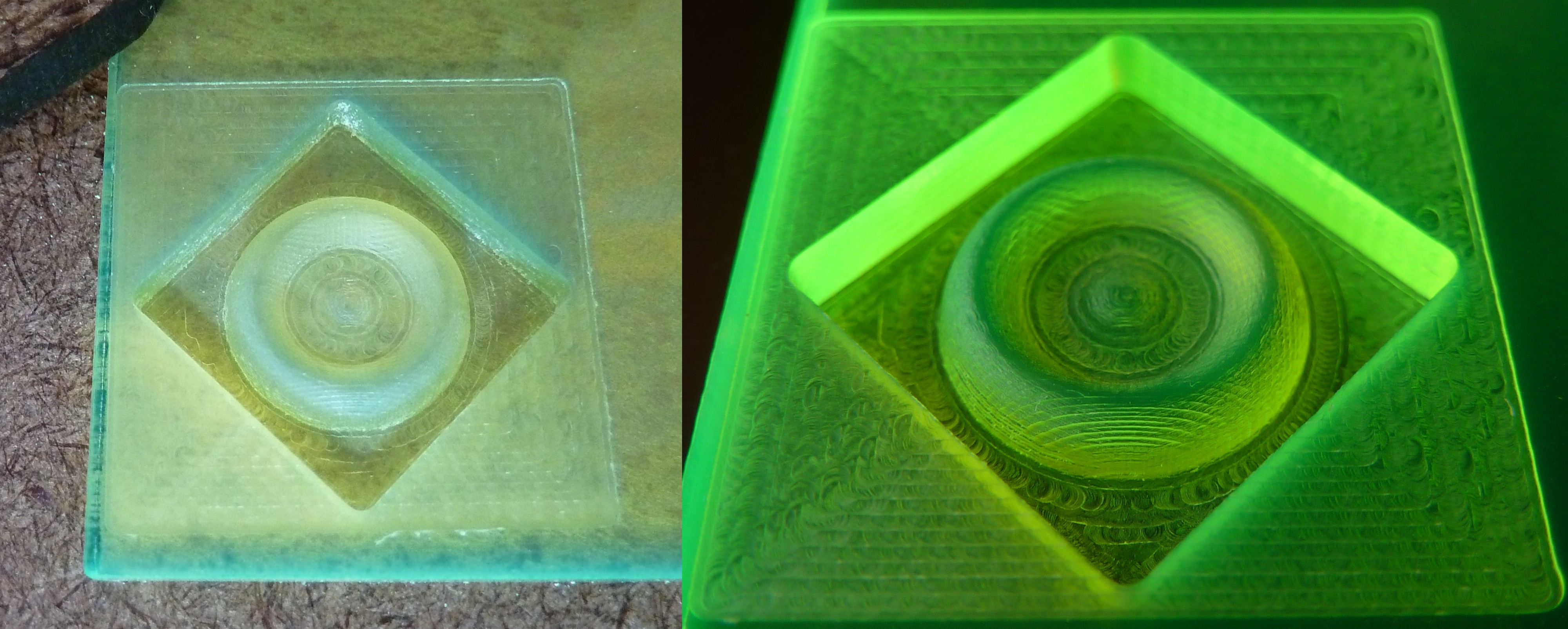
That does look better. Especially the four sides of the pocket.
The face cut looks quite regular in the horizontal/X-in-motion quadrants and a little less so in the vertical/Y-in-motion quadrants. I swapped the X & Y motor/screw units before cutting this pocket. I think I beat the crap out of the formerly-X unit while trying to sort this chatter thing. The X axis, which carries Y, has more inertia. Presumably that both aggravates the perilous ratio of screw/load inertias increasing likelihood of chatter, and increases the violence of each "chat". It was starting to sound rough even when running "smoothly". The lesser not-chatter roughness seems to have followed that unit from X to Y, suggesting that the unit has in fact suffered. I'm not sure how, but suspect the brass insert in the plastic slide may have made some wiggle room for itself.
The X & Y screws still have the "flywheels" -- and reduced range of motion. Removing those will test if conventional rather than climb milling suffices to avoid this sort of chatter.
I guess, in principle, I could have made it from "pulling = bad" via "climb = pull" to conventional milling without Dr. Vahid's lit review. But I maintain appreciation for that explanation of how applied force in the direction of motion really absolutely for sure can mess up a self-locking lead screw in some cases and thus the clearer focus on avoiding poisonous combinations or avoiding force in the direction of motion entirely. As opposed to thrashing variations to see if this or that might work without really understanding anything.
Discussions
Become a Hackaday.io Member
Create an account to leave a comment. Already have an account? Log In.