 Dominik Meffert
Now that the arc starter, arc power, stepper driver and printer controller work it is time to test everything together.
In this test I tried continuous mode for melting the powder. The result looked good but was only partially melted solid. By trying out a lower moving speed the result got not really better but the tungten electrode melted due to the heat and no cooling. The 3D printed mounting bracket also melted, what was ok, because it was not designed to withstand high temperatures. I think I will design a watercooled all-metal toolhead in the future which can handle the temperature and prevent the electrode from melting.
I did another test and this time I tried to print a dot matrix with the idea that multiple dots placed close to each other can create a solid structure, which was the case.
I think with this method the amount of heat/energy can be controlled more precisely than with continuous mode:
I could be wrong, but I think with continuous mode there would be only the power (Amps/Voltage Setting) and the moving speed adjustable and with dot matrix mode there would be also the exposure time and space between dots adjustable, what I think could lead to a more precise and reproducable heating. I think it would also be possible to add short cooling time between the dots to prevent the heat from the pulses from adding up on each other what could prevent overheating of the electrode and spreading of the heat in the powder. Maybe doing so could also reduce the width of the printed lines, what would lead to more pecision.
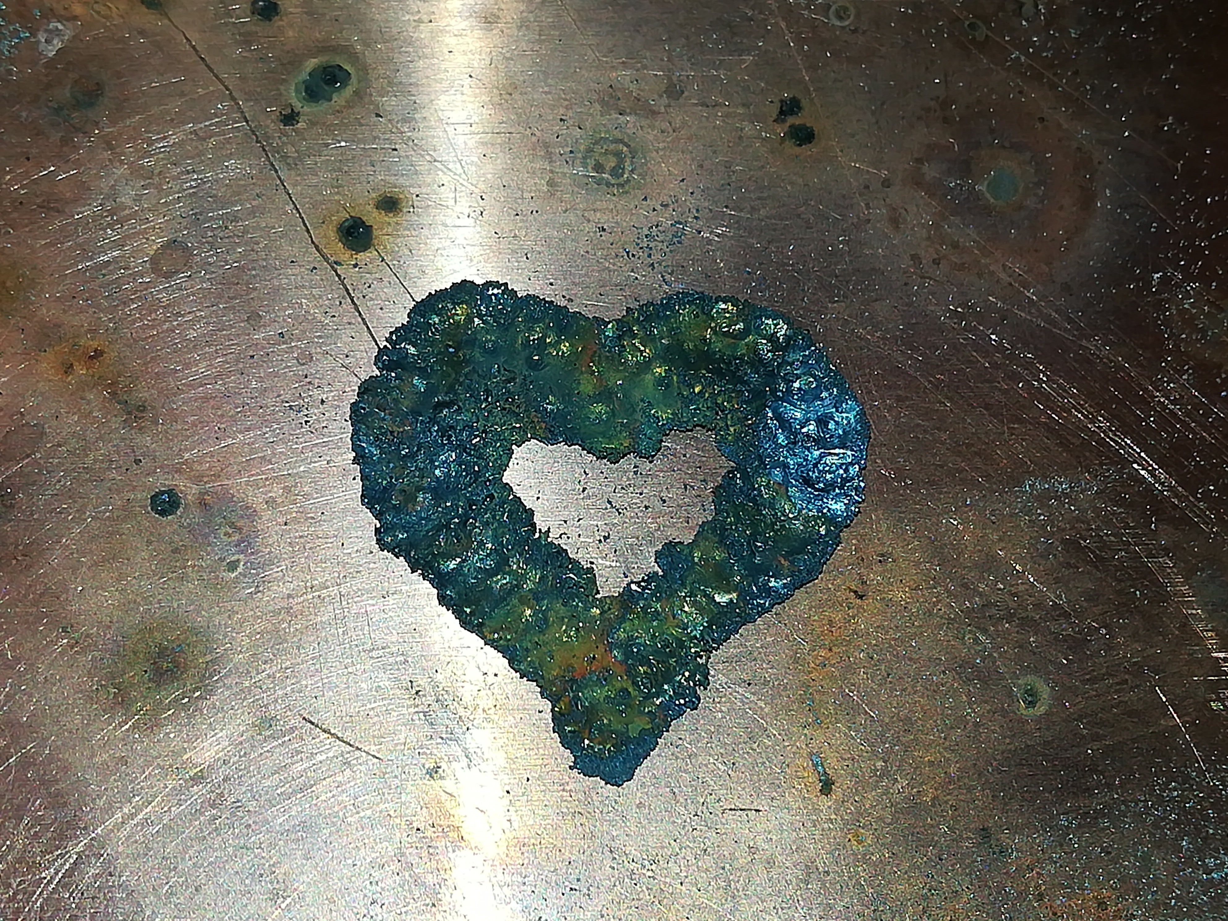
First printed single layer object - there is plenty room for improvements :)
I think a thing that has gone wrong in this test was that the switching of the welding power has been slower than the actual setting. The cause for that is, that I'm currently switching the AC side with a SSR before the rectifier and its capacitor which has to charge and discharge, what I think is slowing down the switching time.
I did that because the SSR was the only semiconductor part which not got destroyed from the arc starter.
I replaced the continuous arc starter with a single pulse arc starter a while back and did not try another MOSFET out. Maybe it would work with the new arc starter and I will test it out in the next few days.
Fried MOSFETS were a huge problem in the construction of this project.
The first time I got the new arc starter to work the MOSFET got fried after some time, I assume from ESD on the gate.
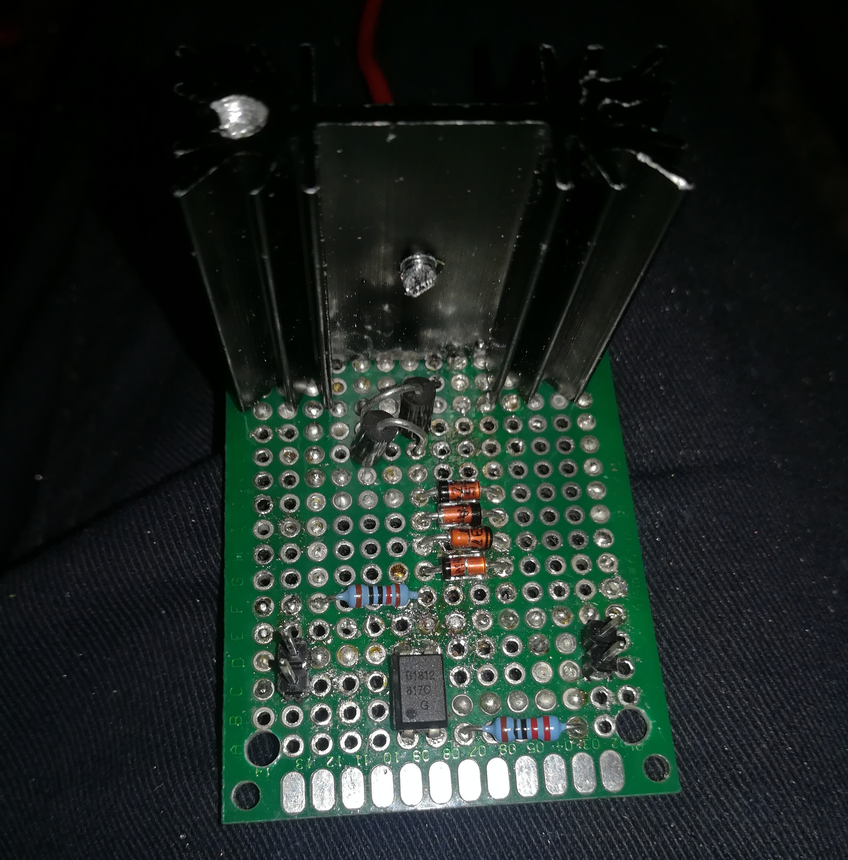
I designed a new pcb with four 7.5V zener diodes between gate and source to clamp the voltage to 15V and two 265V TVS diodes between drain and source to clamp the voltage to 265V. The MOSFET is a IRFP460 driven with 12V.
This MOSFET board switches the arc starter and maybe such a board would also work for the arc power.
I hope this design will last long, because I have no idea what else I could do to prevent the MOSFET from dieing.
Discussions
Become a Hackaday.io Member
Create an account to leave a comment. Already have an account? Log In.