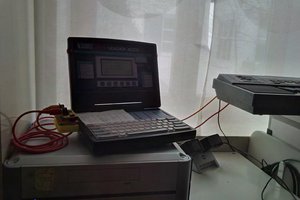
Phase 1: Prove the Z80 works.
Simple wiring with data pins pulled low (nop) and address pins counting on leds. Very excited to see the clock and read wave forms on DSO. Clock is a simple astable 555 circuit. Heavily leaned on Robin Mitchell's project on maker.pro to make this happen.

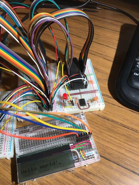
Phase 2: Hello World!
Run a simple assembler program using Arduino harness for ROM and another Arduino to output IO writes. Couldn't have done it with Doctor Volt's Retro Computing project on Arduino Project Hub. Added my own critical update to his code (err, Hello World needs an exclamation mark Doc). Learnt so much about ATMEL port level access from Doctor Volt's code - forever grateful!
 |  |
Phase 3: ROM/RAM module
Still bread boarding, but was a lot of fun building a module that de-multiplexes memory IO and also throws the Z80 into a wait state (BUSREQ) when I hook an Arduino to the module for an EEPROM write. Memory module on left (SRAM on bottom, EEPROM centre and a 74LS139 decoder at the top).

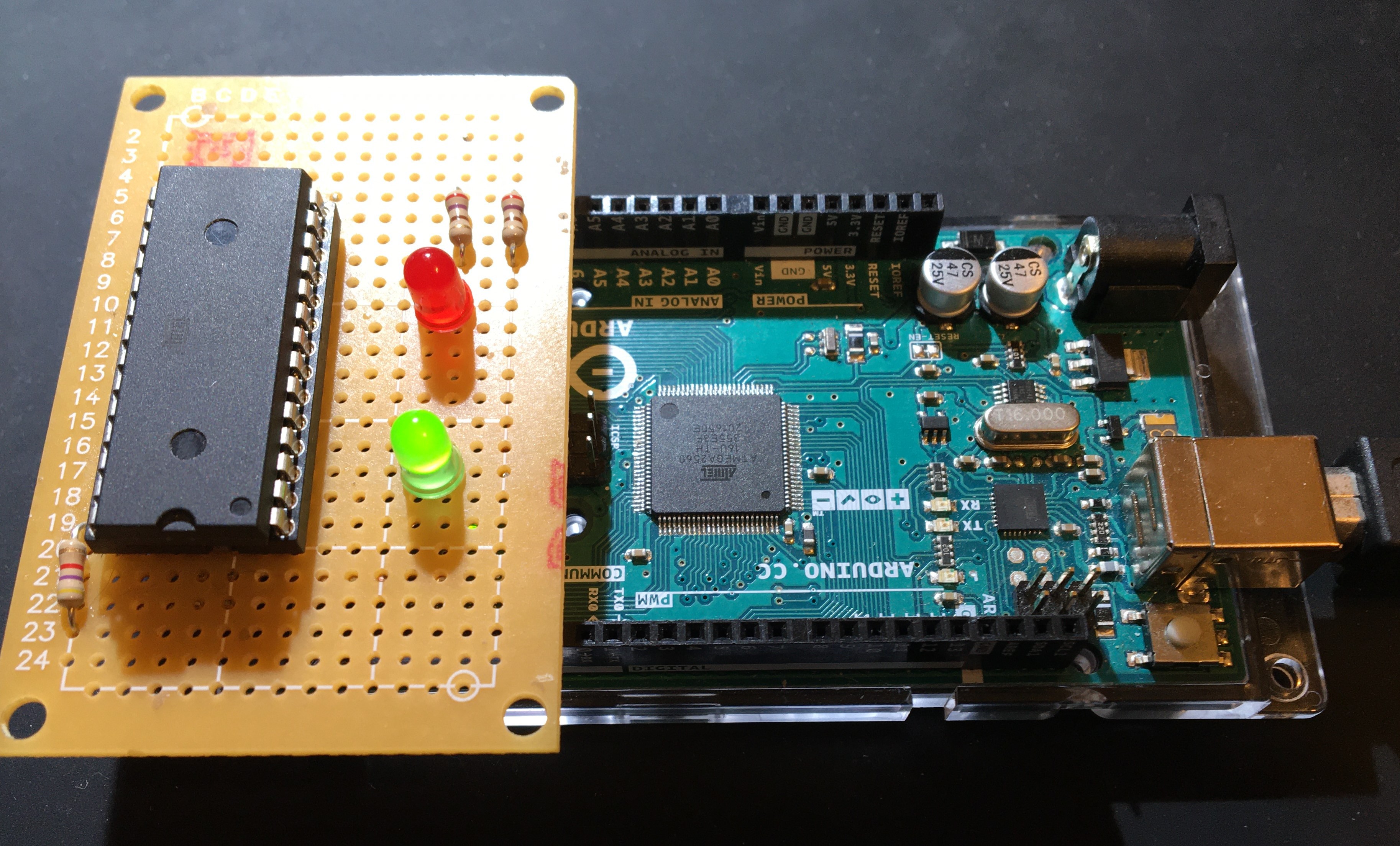
Phase 4: Look ma, no micro-controllers!
Looking at some of the other SBCs out there, I decided that as part of my quest to remove the micro-controllers from my Z80, that I should also rebuild it to get the wiring a little neater. Finally, success! Includes a reset button, BusReq switch for when I want to load new ROMS, and an EA DOG LCD screen that just after I got correctly working, I managed to break. New one on order.

... with a new LCD!

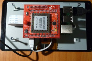
So wiring an arduino in, pulling BusReq low and loading EEPROMs got old, quick. So I've built a simple little EEPROM programmer shield for my mega. I need to practice soldering a LOT more, but this is a good start for the huge amount of soldering required for the SBC. Heavily leaned on Oddbloke Geek Blog for this. Works nice!
 | 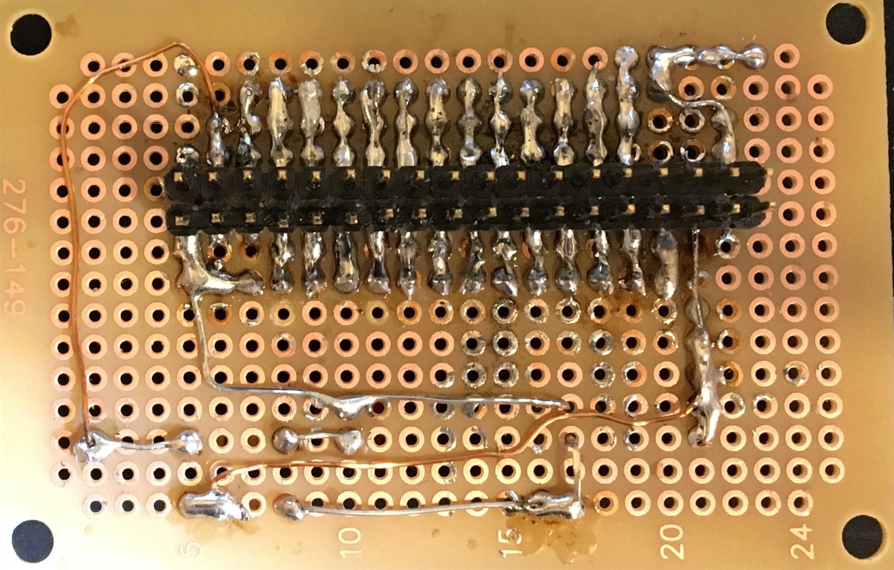 The ... not-so-pretty side |

 Bernhard "HotKey" Slawik
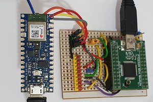
 Tim
Tim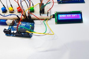
 Dorijan
I know what you mean, I should have done it back then too. But honestly, I couldn't afford it back then, making like $8/hr. Ironic that I can only now afford to become the hobbyist I always wanted to be.
Looks interesting, keep us posted.