This machine appears to have been built using the Jan 1960 Electronics Illustrated version of the plans as the starting point. Other magazines such as Popular Electronics have different descriptions of the same fundamental circuits. Member @Yann Guidon / YGDES has published several logs going into the historical detail of the design.

Compared to the published machine, the Transbiniac has two extra flip-flop modules and a supporting 10K resistor, the multiplication circuit is gone, some of the wiring has been simplified, and there's no AC power supply. I've altered the original overall schematic to reflect the added modules:
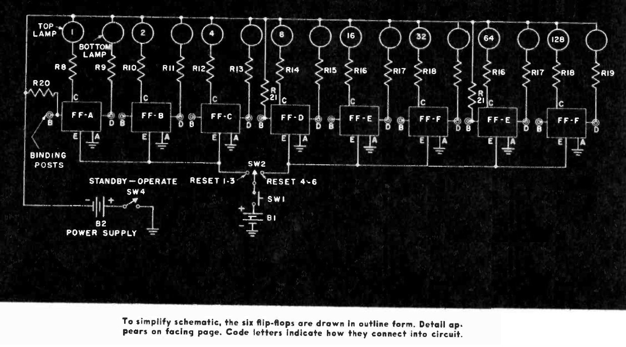
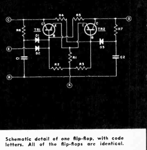
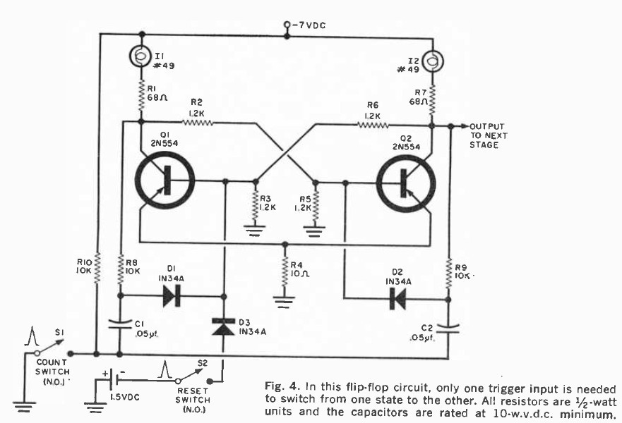
The flip-flops themselves appear to be unchanged from the original published designs. One from the Electronics Illustrated article and another from the March 1961 issue of Popular Electronics:
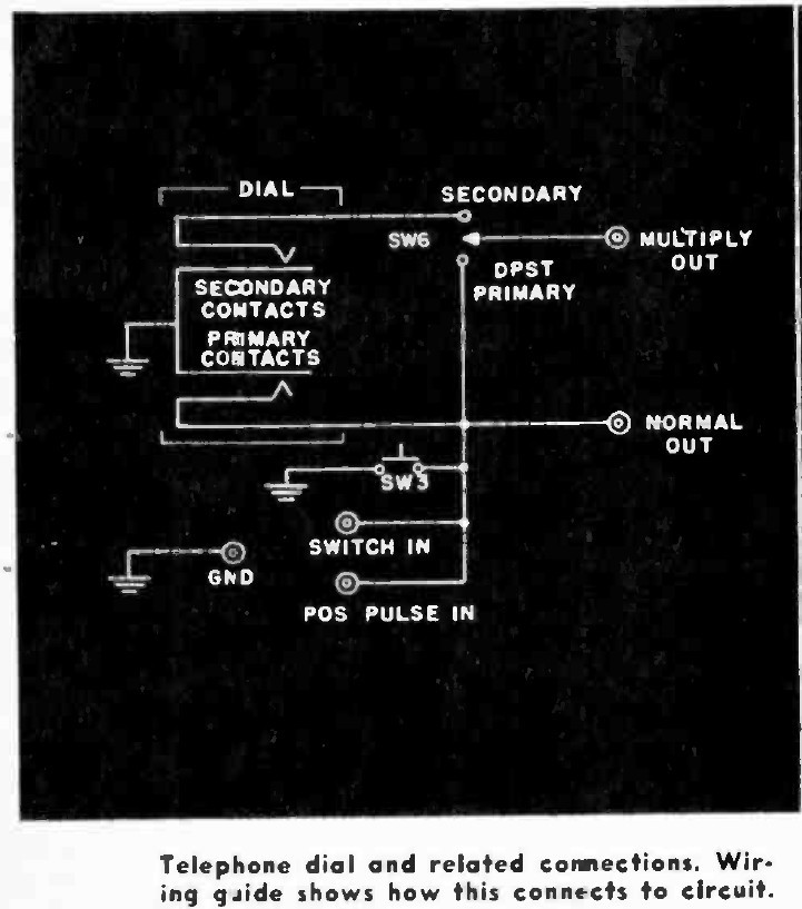
The last change/difference is one I can't tell if it's intentional or not. The original plans call for a normally open trigger circuit consisting of a momentary switch plus a rotary telephone dial. In my machine, the switch and the rotary dial are both wired as NC and don't appear to work in that configuration. My dial also doesn't appear to have the same switch type as the published plans, but my vintage telephone kung fu is pretty weak.
Discussions
Become a Hackaday.io Member
Create an account to leave a comment. Already have an account? Log In.