A BIG BONUS OF NEXTPCB
The NEXTPCB want offer 10 units of this Arduino compatible PCB for your projects in your first order with the link: Earn my PCBs Arduino Compatible.

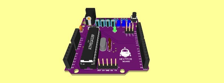
Below is the 3D View of the NEXTPCB Arduino compatible Printed Circuit Board.

Introduction
Introduction
Temperature is a physical quantity that measures the degree of agitation of the particles of a given physical body.
It is an important variable in the physical world that interferes in the most diverse processes such as data centers, chemical and pharmaceutical industries, etc.
That is why monitoring it is extremely important, either to display the values on a display or to issue alerts if the temperature exceeds a certain set point.
So in this article, we will learn how to develop a thermometer with an ATTiny 85, a temperature sensor LM35, and an OLED display.
We will use the ATTiny 85 microcontroller, as it is a low-cost microcontroller and as we will use few I / O pins, it meets our specifications.
Attiny 85 is an 8-bit microcontroller, it features several peripherals such as I2c, SPI, analog inputs, PWM outputs, it does not have native serial communication, but it is possible to emulate it by software.
It features 8 pins, so it is a great microcontroller for portable applications due to its low power consumption.

Therefore, through this article you will learn:
Carry out the assembly of the basic circuit for recording the ATTiny 85 microcontroller on the protoboard with the Lm 35 sensor and OLED display.
- Carry out the assembly of the basic circuit for recording the ATTiny 85 microcontroller on the protoboard with the Lm 35 sensor and OLED display.
Use of a new microcontroller different from the microcontrollers on the Arduino board.
- Use of a new microcontroller different from the microcontrollers on the Arduino board.
How to record ATTiny 85 with the Arduino IDE.
- How to record ATTiny 85 with the Arduino IDE.
Use of the Arduino Uno board as an ISP recorder to record the ATTiny 85;
- Use of the Arduino Uno board as an ISP recorder to record the ATTiny 85;
Earn your first NEXTPCB Arduino Compatible Board.
Now, we will start the complete presentation of the development of the Thermometer project with the ATTiny 85 and OLED display.
Developing the Thermometer Project with the ATTINY85 Microcontroller and OLED Display
Developing the Thermometer Project with the ATTINY85 Microcontroller and OLED Display
As previously mentioned, the project consists of creating a thermometer with the ATTiny 85 microcontroller, OLED display, and the LM 35 temperature sensor.
Before starting to assemble the ATTiny 85 circuit for recording on the protoboard, we will perform some procedures in the Arduino IDE to be able to record ATTiny 85 with the Arduino IDE.
Step 1: Copy the URL below:
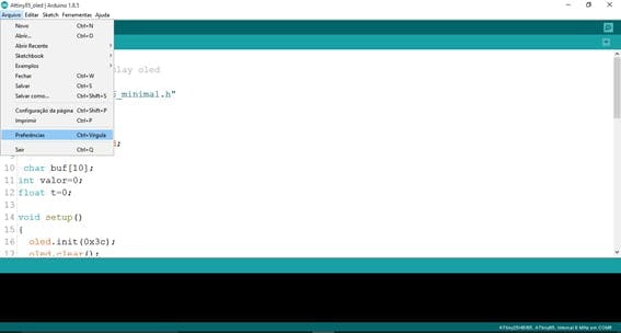
Step 2: Open the Arduino IDE click on Files -> Preferences as shown in figure 2
Step 3: After clicking on preferences it will open the screen of figure 3. In additional URLs, we paste the URL copied in step 1.

Step 4: Click ok and click Tools and boards and board manager as shown in figure 4.

Step 5: After clicking on board manager, the screen of figure 5 will open and we will type Attiny85.
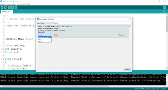
Step 6: Select version 1.0.1 and click on install, wait for the process to complete, and click on close.
Step 7: Close the Arduino IDE and open it again to check if ATTiny 85 was installed correctly.
The installation of Attiny on the Arduino IDE has been completed, now we are going to perform the assembly on a protoboard to perform the recording of a sketch blink with Attiny85 first.
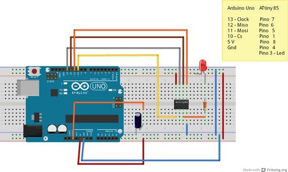
For recording the sketch in ATTiny 85 we will use the SPI communication of Arduino Uno and Attiny 85.
That's why we set up the recording circuit according to figure 7.
Pin 5 V of Arduino Uno goes to pin 8 of Attiny 85, GND pin of Arduino Uno goes to pin 4 of Attiny.
To prevent the Arduino reset while recording the Arduino, we place a 10 uF capacitor between the Arduino reset and the GND.
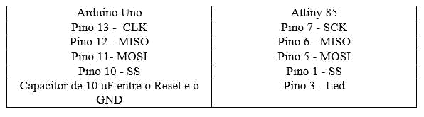
Table with Arduino Uno connections on Attiny 85.
Next, we will start the ATTINY recording process.
Sketch recording Arduino ISP in Arduino Uno
Sketch recording Arduino ISP in Arduino Uno
As previously mentioned, we will use Arduino Uno to record the sketch on ATTINY85 through SPI communication.
To do this we will first record the Arduino ISP sketch on the Arduino Uno so that we can use the Arduino Uno as an ISP recorder.
For this, we will follow the steps below as shown in figure 8.
For recording the Arduino ISP sketch on the Arduino Uno you can disconnect the capacitor from the reset pin.
1st: Click on Files -> Examples -> Arduino ISP -> Arduino ISP

2nd: Sketch Arduino ISP

3rd: We recorded Sketch on Arduino Uno.
In the recorded sketch we put the capacitor on the reset pin according to the schematic circuit of figure 7.
Writing the blink code on ATTINY85
Writing the blink code on ATTINY85
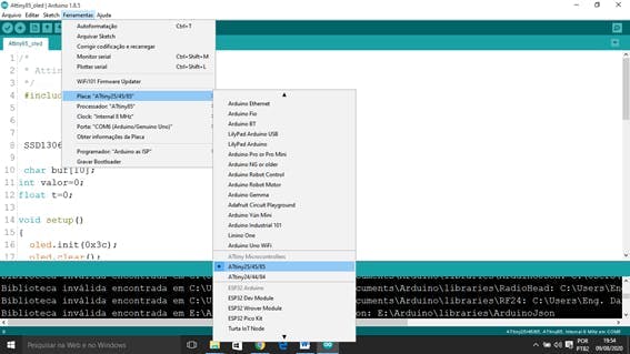
Write the code in the Arduino IDE and we will select some settings in the Arduino IDE as shown in figure 11.

In tools, we select the ATTINY85 board.

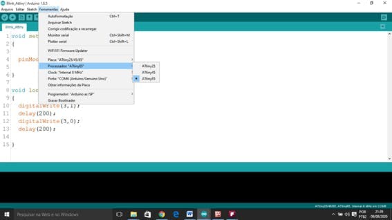
We can change the microcontroller clock to 8 MHZ or 1 MHz.
If we change the clock we have to record the bootloader for the clock selected in the options record bootloader.

In our example, we will use the internal clock of the ATTiny 85 microcontroller.
We select the port with which our Arduino Uno is connected.
The programmer selected Arduino as ISP.

Ready, we can perform the recording of ATTINY85 and thus flash an LED connected to pin 3.

After recording, the led will flash every 200 ms.
Thermometer circuit with ATTINY85 and LM35 sensor and OLED display.
After blinking with the ATTINY85 we will add a temperature sensor to the LM 35 and an OLED display to display the temperature values and an LED to light up when the temperature reaches a set point.
Temperature sensor LM35
Temperature sensor LM35
The sensor used for temperature measurement is the LM35, an analog temperature sensor that has a sensitivity of 10 mV every 1 ºC.
That is, for every 1 º that the temperature varies, the output voltage will vary 10 mV at its output.

Pin 1 of this sensor is the positive DC power
Pin 2 - Output signal
Pin 3 - GND negative supply.
To perform the temperature reading, we will use the analog input of the ATTiny 85 microcontroller.
The Attiny digital-analog converter has 10 bits of resolution, that is, the input value can be divided into 2 ^ 10 levels = 1024 levels.
For a 5 V input we will have 5/1023 = 0.00488 V, 4.88 mV.
Each level has 4.88 mV.
To calculate the temperature value we will use an equation:
1º C - 10 mV
25 ºC - 0.25 V
First we have to calculate how many bits we have in 0.25 V, we calculate using a simple three rule
5 V – 1023 values
0, 25 V – y
y = 0, 25. 1023 / 5
y = 51 values
To calculate the temperature value we will do
Temperature = y. 5/1023. 100
Temperature = y. 4, 88 mV. 100
Temperature = 51. 4, 88. 10 ^-3. 100
Temperature = 25 ºC.
Multiply by 100 to find the temperature in ºC.
Then we will use this equation to calculate the temperature value.
Temperature = value read by a / d. 4.88 mV. 100

Table with ATTINY85 connections.

The ATTiny 85 pins share other peripherals as well, so pins 7 and 5 are not only SPI communication pins but also have I2C communication.
Not forgetting to put the capacitor on the reset pin and on the GND on the Arduino Uno.
The display used will be an OLED I2C display, as it is a display that consumes little energy and uses few pins for communication.
After the assembly, we will program our ATTINY85.
ATTINY85 code
ATTINY85 code
To communicate with the OLED display we will need to include the SSD1306 minimal library that can be downloaded from this link:
After downloading and installing the library on the Arduino IDE, we can write the code to program Attiny 85
We first include the SSD1306_minimal library, declare the OLED object, and declare global variables for calculating the temperature and then transform it into a string.
#include "SSD1306_minimal.h"
SSD1306_Mini oled;

char buf[10];
int valor=0;
#include "SSD1306_minimal.h"
SSD1306_Mini oled;

char buf[10];
int valor=0;
In the void setup function, we configure pin 3 as an output and initialize the OLED display with the address 0x3C and clear the OLED display.
void setup()
{

oled.init(0x3c);
oled.clear();
pinMode(3,OUTPUT);

}
void setup()
{

oled.init(0x3c);
oled.clear();
pinMode(3,OUTPUT);

}
In the void loop function is all the logic of the program, we read the temperature sensor, check if the value is greater than 27 ºC if it is lit the led, if we do not keep the led off, we write the temperature value on the display OLED.
void loop()
{

valor = analogRead(A2)*0.00488*100;

if(valor>27)
{
digitalWrite(3,1);
}

else

{
digitalWrite(3,0);
}
void loop()
{

valor = analogRead(A2)*0.00488*100;

if(valor>27)
{
digitalWrite(3,1);
}

else

{
digitalWrite(3,0);
}
Conversion of the entire temperature value to string so that it can be displayed on the OLED display, the Attiny 85 has little memory, so the function used has been optimized.
sprintf(buf, "%i",valor);

oled.clear();
oled.cursorTo(25, 0); //Define a posição
oled.printString("Termometro"); //Mostra o texto
oled.cursorTo(0, 3); // linha 0 coluna 3
oled.printString("Temperatura: ");
oled.cursorTo(90, 3);
oled.printString(buf);
delay(300);

}
sprintf(buf, "%i",valor);

oled.clear();
oled.cursorTo(25, 0); //Define a posição
oled.printString("Termometro"); //Mostra o texto
oled.cursorTo(0, 3); // linha 0 coluna 3
oled.printString("Temperatura: ");
oled.cursorTo(90, 3);
oled.printString(buf);
delay(300);

}
Results
Results
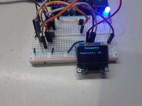
After programming the ATTINY85, we have the circuit in operation according to figure 18.

Conclusion
Conclusion
In this article, we learned how to program the ATTINY85 microcontroller, set up its minimum circuit for operation, use of Arduino Uno as an ISP recorder.
We learned how to use the analog inputs of ATTINY85, the operation of the LM35 temperature sensor.
We have developed a low-cost digital thermometer with a low-power microcontroller.
A BIG BONUS OF NEXTPCB
A BIG BONUS OF NEXTPCB
The NEXTPCB want offer 10 units of this Arduino compatible PCB for your projects in your first order with the link:Earn my PCBs Arduino Compatible.
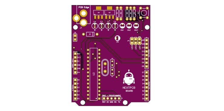
Below is the 3D View of the NEXTPCB Arduino compatible Printed Circuit Board.