Close
0%
0%

Solar Node Swiss Army Knife

...an unopinionated approach to self-sufficient systems.

Similar projects worth following

This board is more than just a simple solar charger.

It prioritizes flexibility/modularity over efficiency.

Features Overview


Power Input

  • 2.4-15V input from solar cells or other power sources
  • Adjustable Maximum Power Point Control (MPPC)

Charger

  • Undervoltage protection when the battery overdischarges
  • Overdischarge current protection
  • Overvoltage protection when the battery overcharges
  • Overcharge current protection
  • Battery temperature sensor
  • Compliant with JEITA charge temperature specification
  • Battery fuel gauge
  • Battery capacity adjustment with aging/temperature

Other Features

  • Holder for a single AA sized Li-Ion or Li-Po battery
  • Real Time Clock
  • I2C level shifter
  • ESP-01M WiFi module (optional)
  • I2C programmable Buck Regulator 0.6-3.75V (1.8V default) Current Limit: 100-400mA
  • I2C programmable Buck-Boost Regulator 1.8-5.5V (3.3V default) Current Limit: 100-800mA
  • "Shipment Mode"
  • Breadboard friendly design
  • Multiple mounting options

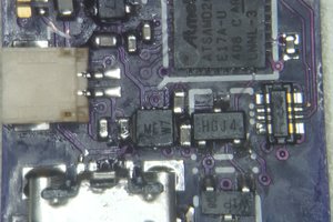
IMG_0069.JPG

prototype closeup

JPEG Image - 718.03 kB - 11/02/2020 at 19:09

Preview
Download

IMG_0073.JPG

prototype asssembled on case without battery

JPEG Image - 758.31 kB - 11/02/2020 at 19:08

Preview
Download

proto_back.jpg

prototype unassembled back

JPEG Image - 231.90 kB - 10/20/2020 at 17:30

Preview
Download

proto_front.jpg

prototype unassembled front

JPEG Image - 210.52 kB - 10/20/2020 at 17:29

Preview
Download

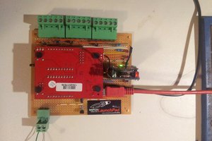
lls1-test-jig.jpg

testing jig assembled

JPEG Image - 730.48 kB - 09/28/2020 at 13:46

Preview
Download

View all 7 files

  • Project Update

    Leonard Pollak08/14/2021 at 17:28 0 comments

    I have changed this projects status to "shelved" as most of it's core components/functionality can now

    be found in my new project LLS3.

    The reasons for this are the following:

    The title reads "unopinionated" which it really wasn't.

    It had the albeit optional footprint for the ESP-01M footprint and that kind of bothered me.

    I also found the AA sized LiPo cell was probably a bit too much for some projects.


    Up until now this prototype was good for developing and testing but I decided to move on

    and *really* make it unopinionated module that can be used on a breadboard or soldered onto a PCB.

    In the future this project will be revived as something more like a protoboard with an an MPPC IC,

    an LLS3 module and who knows what :)

  • Prototype Update

    Leonard Pollak11/02/2020 at 19:46 0 comments

    After tinkering around with it for a while I was able to identify some issues with it.

    Some of them are an easy fix, others will require some more attention.

    The good news is that the main functionality (charger IC) appears to be working just fine so I was

    able to write a micropython driver for it (see here).

    The driver needs to be built into the firmware as a frozen module because of memory reasons.

    The bad news is that the I2C level shifter and the MPPC IC are not connected in the way they

    should be but I might be able to fix that with a bit of hot air and a steady hand.

    I was also thinking about writing a proper Tasmota driver as well since I think it is a device that fits

    well into that ecosystem. However I have no experience with the Tasmota API so that might

    take some time...

  • Prototype sneak preview

    Leonard Pollak10/20/2020 at 19:38 0 comments

    Today the prototype was shipped and it will arrive in one week. Yay!

    I've uploaded the pictures the factory sent me.

    I decided against soldering the SMD components myself, since I am not confident  in

    my abilities to solder components of this size.

  • testplatform/prototype update

    Leonard Pollak10/18/2020 at 08:46 0 comments

    LLS1 Testplatform

    lls1-testplatform-code was updated and should now be ready for testing the prototype.

    Since ampy occasionally crashes, i decided against using it and incorporate the MicroPython scripts into the firmware itself instead.


    Prototype

    The assembly is in progress and it should arrive in the 1st week of November if everything goes well with shipping...


    MicroPython Firmware

    The MicroPython scripts development will start as soon as the prototype arrives.

    there will be two MicroPython firmwares:

    1. testing device functionality
    2. "production"

    Test Firmware

    • connects to WiFi, gets current time and saves it to the RTC
    • sets an RTC alarm
    • sets voltages to 3 V and 2 V
    • prints TEST_OK if everything went well
    • prints TEST_FAIL if something went wrong

    the RTC alarm will be read by the Raspberry Pi

    the voltages will be verified by the Raspberry Pi

    Production Firmware

    • contains all necessary drivers
    • opens a WiFi AP
    • starts a WebREPL
    • starts a main loop printing some device info

  • test-platform code update

    Leonard Pollak10/04/2020 at 20:33 0 comments

    the test-platform code is publicly available here: https://gitlab.com/leonardp/lls1-testplatform

    TODO:

    • code for flashing esp firmware
    • verify successful firmware upload
    • MicroPython test-firmware
    • code for uploading MicroPython Firmware
    • test it all with the prototype

    the estimated time of arrival for the prototype is at the end of October...

  • Update for the Testplatform

    Leonard Pollak09/27/2020 at 18:55 0 comments

    added pictures for the test/programming platform.

    it's a raspberrypi shield (obviously)  and the sd image is build with nixos (see: lls1-test.nix).

    pictures of the assembled testplatform and the code running on it will follow soon...

  • Current Status and TODO

    Leonard Pollak09/24/2020 at 13:48 0 comments

    Done

    • Testing Jig PCB Design
    • Testing Jig PCB Order
    • Testing Jig Parts Order
    • Prototype PCB Design
    • Prototype Order

    TODO

    • Testing Jig RaspberryPi Image
    • Test Procedure Flowchart
    • Testing Jig Code
    • Prototype Code (Micropython ESP8285)

View all 7 project logs

Enjoy this project?

Share

Discussions

emporary wrote 02/27/2022 at 19:20 point

Everyday life can be tough. But with the Army Knife, it doesn’t have to be. This soft armor is made by heavy-duty material, a saw for all materials, scissors, and much more. Made from stainless steel, the Army Knife is made to help you tackle any situation life throws at you.

  Are you sure? yes | no

Similar Projects

Does this project spark your interest?

Become a member to follow this project and never miss any updates