 Open Technology
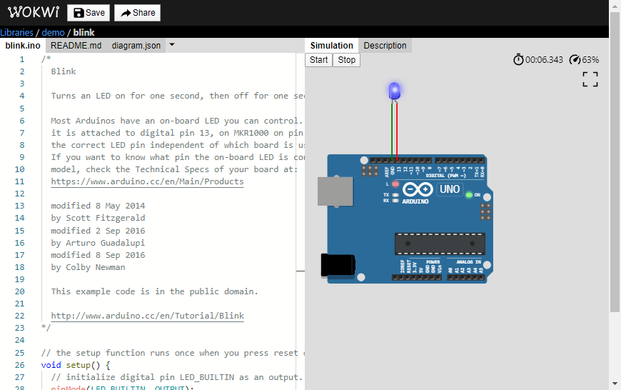
Here is how the Arduino Simulator looks on a web browser. All editing is done in the left panel. The sketch, The connections, the project details, the header files, etc can be edited ✍🏽 Third-party library files/source files can be edited or added. This is one of the key features of the wokwi Arduino Simulator.
The three files of the example project are briefed here:
- blink.ino - The sketch can be edited here. The examples code from other sources/websites can be pasted here directly to see how they run.
- Readme.md - Not a mandatory file but a useful practice to help yourself and others 😀 to give a brief description of the project
- diagram.json - Heart 🩺 of the connections. here is where you will call all the elements (LEDs, UNO, Mega, Sensors, things, and stuff like that. You tell the Wowki Simulator on where to connect them here.
The first files are straight forward and hence we will focus on the third file 🎯. In the next step, we will see the basic layout and sections of the diagram.json file.
Tip: diagram.json holds the key information about the connections. The file name should not be changed (as of date)
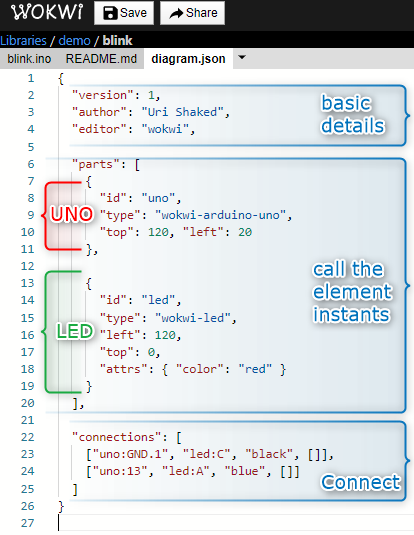
As you can see, at a higher level, in the wokwi Simulator we have the following three sections
- Basic information (something similar to metadata) - This is only for the information to give credits to the original co-author, mention the version)
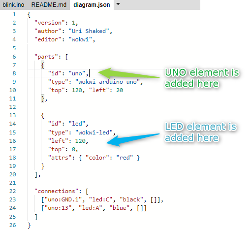
- Parts section - Here is where you can add ➕ the parts, here known as wokwi elements.
- Connections - You will connect the individual elements (complete the circuits)
In the next step, we will play around a little in the *.ino and the diagram.json tabs in the editor panel.

A small change🌀 is done in the Arduino blink sketch. The delay🐾 is reduced. you can try something different too.
We will now jump to the diagram.json window, I would say the heart of the wokwi Arduino simulator. 😀
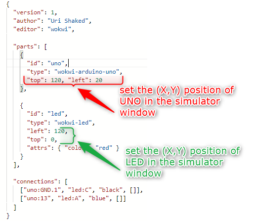
The script file is easy to read and edit. The parameters can be kept all in one line or split into multiple lines(my favorite). As long as the script structure is followed with the appropriate code, it is fine.
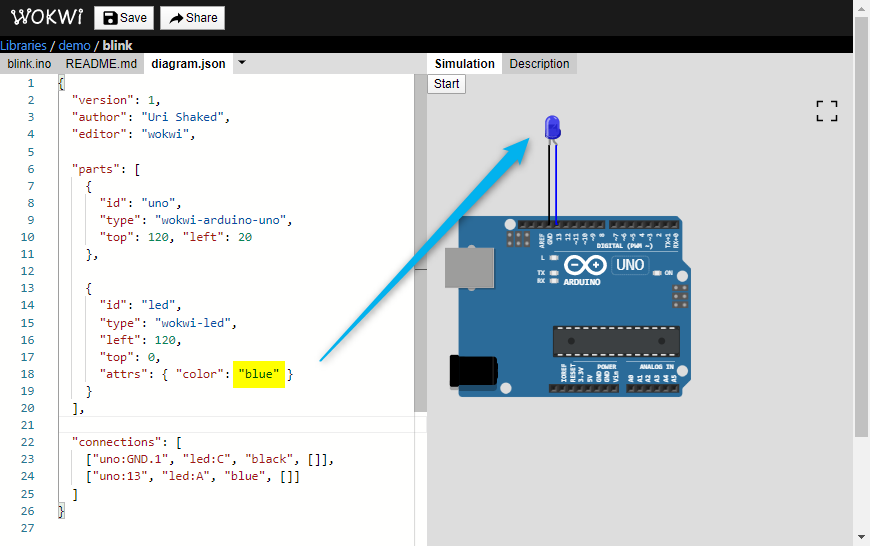
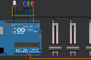
In another step, I changed the red LED to a blue one. Simulation window gets updated immediately.
After changing the color parameter in the editor pane, the LED in the simulation window changed to blue 🟦.
In the next step, we will see the connections. This is the final step in completing the circuit. ⭕
----------

- The color of the wire can be changed
- The pins of the Arduino are pointed by UNO:1 or UNO:3 fro pin number 1 or pin number 3
- "uno" and "led" are the ID names. It can be literally anything. Meaningful ids are better
- The LED pins can be accessed as follows
- led:A - Anode pin
- led:C - Cathode pin
Note: The LEDs will work in the simulation as it is, but wait, in real life, we have to limit the current through the LED.
As of now, that's all. Our next step is to just hit the "START" button. 😀
Press the START button to start the simulations. thank you for following the last step 🏁. if fact, this is the first step in getting involved in simulations, coding, open-source community coding, and beyond. 😅
Please spread the word about our Wokwi Arduino Simulator. For today, it is still a work in progress. It is getting better week by week.
Many people have directly and indirectly contributed to the Simulator. Many thanks for that. Please share your feedback via comments or direct messages. We will be glad to simulate 😉that!
Thank you 😀
 John Macrae