 Xasin
XasinWhew, so that was a few eventful last few days working on this present!
I had some extra free time on my paws thanks to a Uni project wrapping up, and I feel like I used it quite well~
Plus, with a slightly adjusted, calmer style of meditation, things actually went by quite smoothly!
Anyhow, let's catch you guys up.
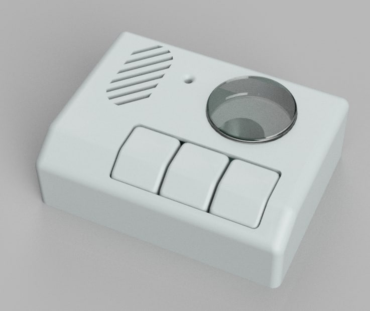
First things first, last Thursday I spent the whole afternoon chipping away at the 3D model of the casing. Using Fusion360 and the KiCAD STEP file of the PCB it actually was a very smooth process to design something cute looking!
I will want to switch to FreeCAD with Realthunder's changes soon, but for now I can still comfortably use Fusion360, so whatevs.
Here's a screenshot of the almost-complete casing, give or take some of the multi-material changes for the buttons:
Apart from just designing this casing, we also put a bit of time into actually printing it - there'll be pics later~
We also finally got the materials for the PCB as well as a time-slot in the Uni laboratory to solder it.
Due to the lockdown students have to register for a reserved timeslot, that took a moment. The end result was well worth the wait though!
I did end up leaving out the battery charger and fuel gauge, for the simple reason of having messed up the footprint of the battery. It used the smaller variant of the two QFN footprints available, which frankly scares me a bit because it still does dissipate a fair bit of heat when dropping 5V down to the LiPo voltage to charge it!
Oh well - everything else fit beautifully, and here's the almost-assembled board, sans the ESP32!
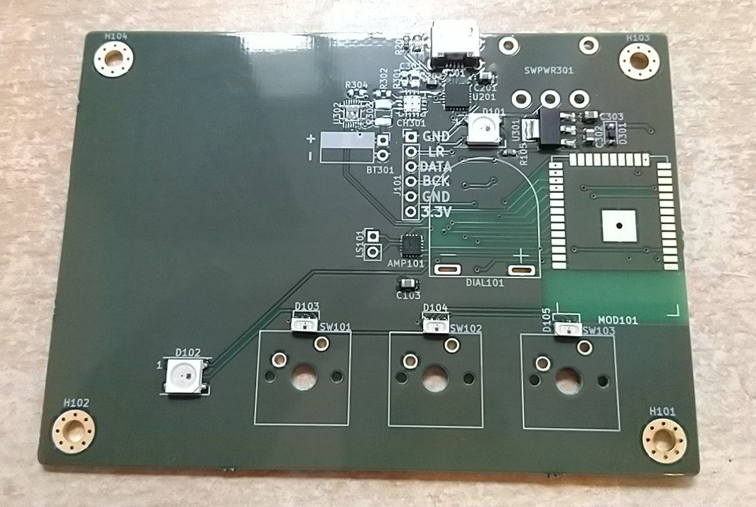
The missing charger footprint is the one in the top middle... Oh well.
Oh yeah, and the LEDs I'm using to illuminate the key switches? Those are side-mount Inolux WS2812 clones, which can also be mounted in the upright position to create this neat tiny-form-factor directed LED. Works great!
All in all, the PCB + components fit into the casing exactly as I was hoping. After tweaking the program code, checking that everything boots without blowing up etc. etc, I finally ended up with this extremely promising WIP of the assembled unit.
Ain't she a beauty <3
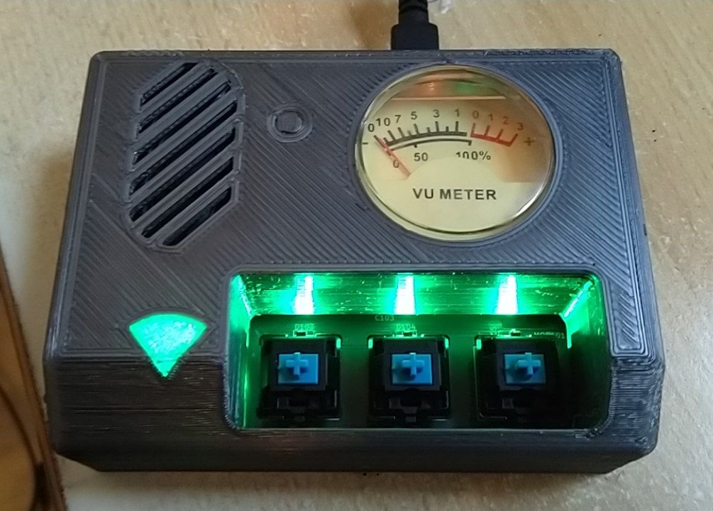
There still are some quirks to sort out. The VU Meter is connected the wrong way around so sadly the needle moves down onto the scale instead of up, aw for that but nothing major.
The speaker and sound is quite good though! I mean, for this setup. I wish I would've taken audio design more into account for this because it's lacking a bit of bass, but for human speech it is very understandable and quite crisp.
It also looks like the power design I made supports the WiFi at full power, that'll help keep the stream of MQTT OPUS packets flowing smoothly.
"All" that's left to do now is:
- Connect the Microphone
- Write a I2S Microphone to Opus stream class (kinda easy tho)
- Read out the buttons and write the recording user-interface
- Write the Ruby server side that saves and streams the audio recordings.
Hoo boy... Well, it's a lot of fun and we're in no rush, so let's see where this goes!
Discussions
Become a Hackaday.io Member
Create an account to leave a comment. Already have an account? Log In.