 Inne
InneNote
This project log is for everyone that wants to know what happened with the soft soldering jig since the last update. If you are mostly interested in the newest files please hold out for a bit; in the coming week I will be publishing the files for version 3 (v3) of the jig.
Renewed interest
It is good to be back. After being featured on the Hackaday blog and podcast (ep213) last week, my motivation has very much returned. Since I last submitted something, in 2020, I have been working on and off on this project doing bits and pieces. This post is to catch up with what has happened since then, what works, what needs improvement and what my goals are for this project. Sprinkled with a bunch of pictures to keep it entertaining.
Festivals and talking to people.
In 2020 this project won a prize in the special category (best jig) of the circuit sculpture contest. It was a really validating experience, and really felt like something I made was appreciated and celebrated.
In the years after, I kept taking the jig to Makerfestivals and Hackercamps. Both to solder on and to show as part of my portfolio. They came in handy many times, though not as often yet to make actual circuit sculptures.
One of the coolest things was when someone asked me if this could be used to mix fluid droplets for microscope. We tested it on the spot, and it worked pretty well. It was really interesting to hear the feedback, whenever I showed the soft soldering jig.
All and all, I am very happy I wrote up this project page. Consistent writing and documenting doesn’t come natural to me. However, having all the files and photos in one place, somewhere that you can point someone to, has been great. I am glad I did it, and can recommend to everyone making a project to give it a try and see where it goes.

A look at the technical side
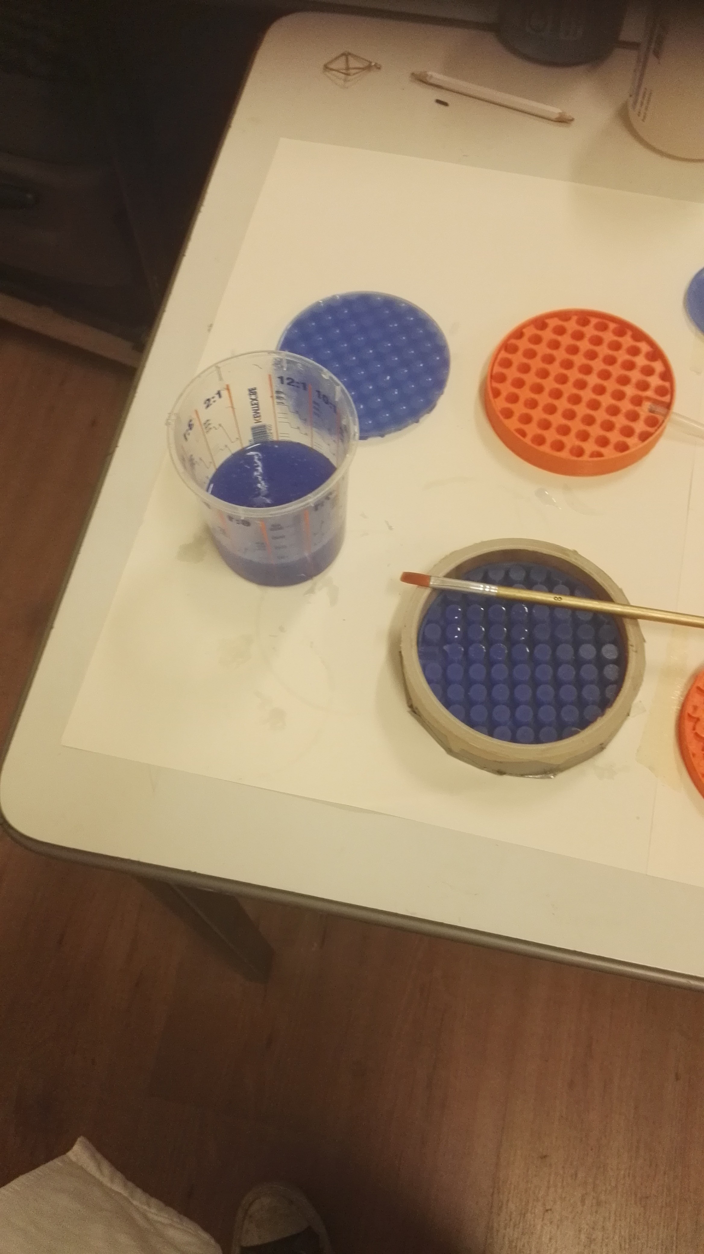
Time to look back on the Hardware. As of posting, there are 3 versions of the jig, v0, v1 and v2 with v3 coming shortly. V0 is cute, small and has working vacuum. V1 is the main design, has top and bottom layer and doubles as fidget toy. For v2, the mold has brass rods inserted, instead of 3D printed ones, they make me less sad when they inevitably break in transport, as opposed to v1. The following are the lessons learned along the way.
The vacuum suction system
As it stands, the vacuum system is a major failure. The core principle doesn't work, it was supposed to hold SMD components in place so they wouldn’t stick to the soldering iron. There are however too many (man)holes to create proper suction. You would need to cover all of them. Even with the v2 model with fewer holes, you would still need to plug them all, which is too much work.
Initially, I was hoping the air pumps would be strong enough, and the (man)holes tiny enough, that the suction was sufficient. However, even once you plug all the holes, the silicone is too flexible to withstand the vacuum and will cave in.
Therefore, the SMD hold-in-place system needs a redesign. This can be either vacuum or something completely different. Since there are other, more pressing, design challenges; I decided to remove the complete underside from the jig (for v3). Even though, suction does work for v0. Removing the underground saves a lot time on production and makes everything easier to work with. See Picture 2 to get an idea of what assembling them involves. It shows connecting the top (above ground) and bottom (underground) parts for jig v1.
 |
 |
 |
 |
 |
The good things
During use, these where the things the jigs performed really well at. It is excellent if you want to solder directly on the table. Interestingly, common tasks in general soldering, like connecting wires or soldering components with leads, work well. It also provides a (flat) surface to solder PCBs on the go.
Circuit sculpture wise, I am content with how well the jig holds brass rods in place. The flexibility of the silicone makes it easy to place and remove them, this goes very quickly. It turns out that since the silicone springs back to shape so easily (it's compliant), the width of the streets (the lines on the grid) doesn’t need to be precise, and will hold multiple diameters of rods quite happily.
The jigs are also easy to carry and resilient to wear and tear. Especially if compared to the cumbersomeness of helping hands or poster putty which needs to be replenished. Bringing the soft soldering jigs along is delightful.
The number of angles
Almost everyone I show the jigs to tends to give the same immediate feedback: "This is great but I would like more angles." This comment is very fair, and is the next focal point. The main reason this is not implemented yet, is that I couldn’t wrap my head around the complexity of finding the right angles, and how everything would interact. It seems that trial and error will be the preferred method to solve this; with the production time greatly reduced for v3, experimenting angles should be a lot easier.
Jig v0 is special
And then there is jig v0, the initial prototype. It was meant as a minimal proof of concept but it turns out to be very viable in its own right. V0 is quick to print, needs little silicone and the mold is easy to work with. The suction even works, but since the electronics are bigger than the jig, its better to do without. Jig v0 has potential and its concept might be revisited at some point. The production of them isn't shown of yet, so picture 3 shows a bit of the process.
OpenSCAD
The city theme for naming the OpenSCAD variables is fun, and I’ll try to stick with it. Though, I won’t be using it for the small peripheral components like measuring sticks, and hold in place doodads. So it is mainly for the main component, the mold of the soft soldering jig.
 |
 |
 |
Future goals for the soft soldering jig.
From the moment I decided to enter the contest my goal was that: “It would make me really happy if people would use these jigs in the next Hackaday circuit sculpture contest.” So you being able to try one would be a good next goal.
If you want to build one for yourself; version 3 of the jig would be the best place to start. This time around I will try to post updates more bit by bit, instead of aggregating them till complete. The 3D models are there and the jig has both been produced and tested. Pictures still need to be sorted and build instructions (yes we will have those now) need to be written, hopefully in the coming week.
For myself, giving a workshop with them, and getting hands-on experience how other people use them would be nice. Getting some more experience making the sculptures would be a welcome improvement for me as well.
Thank you for reading this lengthy update, and your interest in the soft soldering jig. Also thanks to the Hackaday staff and community for reminding me that this is indeed an awesome project. And lastly, everyone in my local maker network that support me. I hope to show all of you, more of the jig in the future.

Discussions
Become a Hackaday.io Member
Create an account to leave a comment. Already have an account? Log In.
How about "manholes" that default closed? I'm imagining something like molding them closed off at the surface then cut slits that remain closed when relaxed. Stick hollow pegs in where you want to hold stuff. Maybe mold a shallow pocket around the hole so a shoulder on the peg would sit level with the surface. Possibly that would also hold wires/leads perpendicular to the grid?
Are you sure? yes | no
Hi Paul,
This is a cool approach. I can definitely see cutting self-closing holes work. The method you suggest also seems easy to perform. If this fails, molding downward pointing flaps could be an alternative. There is also some improvements to be had by combining the silicone with other materials, like metal parts or 3D printing, as you suggest with the pegs.
I was thinking of revisiting the vacuum, by creating a cavity, like a boiler room or something, under one of the buildings. Then connect that to one of the manholes, so when you press the building you can create suction manually. The self-closing suggestion will help with that I think. In the end the less electronics involved the better
It will probably be quite some research to make it work. Currently I am more in the implementation phase, focusing on small improvements. When I revisit the vacuum, I will give this approach a try.
For building height wise, the holes could be a good starting point, before that I should first figure out how to hold the SMD components though.
Also thanks for reading my updates, your feedback has been consistently great on my projects :D.
Are you sure? yes | no
Happy to read how you're still developing your idea here. :)
"boiler room" connected to manhole -- so 1:1 manual vacuum for each manhole? Avoids pulling air through open manholes and self-contained too!
Are you sure? yes | no