 Grace Qiu
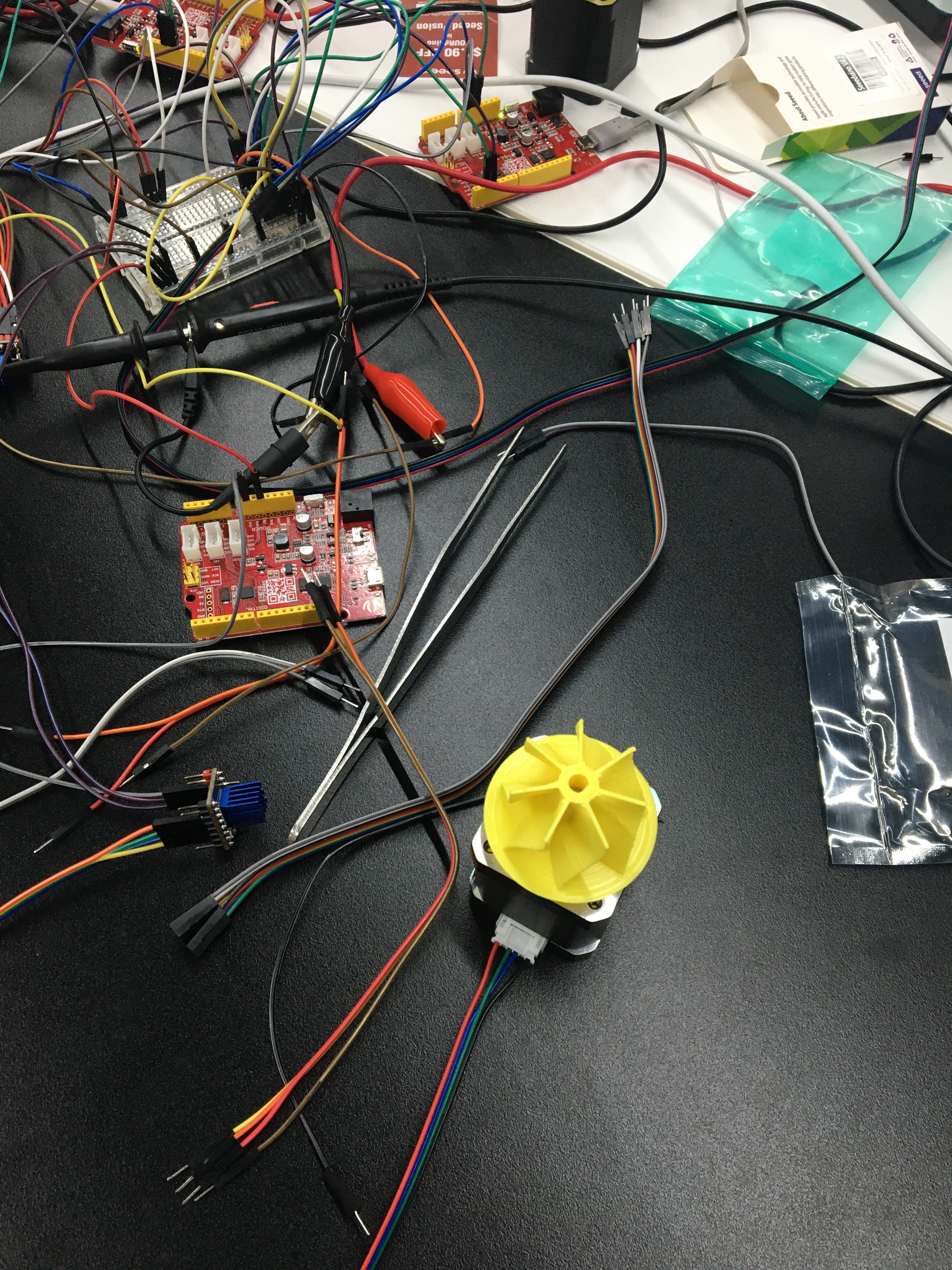
We finished connecting the boards. First, we revisited the data sheets and went over it carefully, knowing each pin's specific meaning and functions. Details are summarized as follows:
- Wires: Black: A1; Green: A2; Red: B1; Blue: B2
- Multimeter:If 2 pins short-circuited, the multimeter will beep.
- Go to official websites, find the model and its design drawings.
- The little silver hump on the chip correspond to different pins
- Only 1 of the 2 PDN is working (use multimeter to test)
- Pin assignments:
- GND: Ground
- VDD:chip's voltage input,connect to Seeduino 5V
- STEP & DIR :used by Seeduino to send signals to step motor driver
- Go to find the datasheet and figure out the assignments of other pins
- Pin assignments
- CLK: Connect to GND to start the internal clock of the chip
- ENN: Enable Not
- EN: Enable
- MS1/MS2: Determine mircostep configuration (1/0 1/1 0/0 0/1)
- DIAG: Diagnostic: detect errors
- VS: Motor Supply Voltage: 9V
- Low:GND,High:5V
- Pin assignments
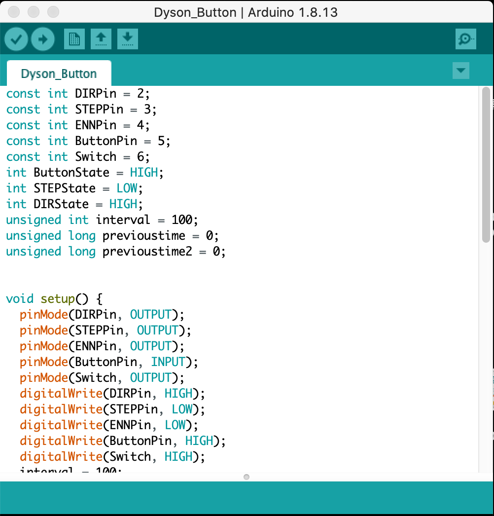
After connecting the boards, we tested it by connecting it to computer, coded on Arduino, and tried to see if our motor was functioning.
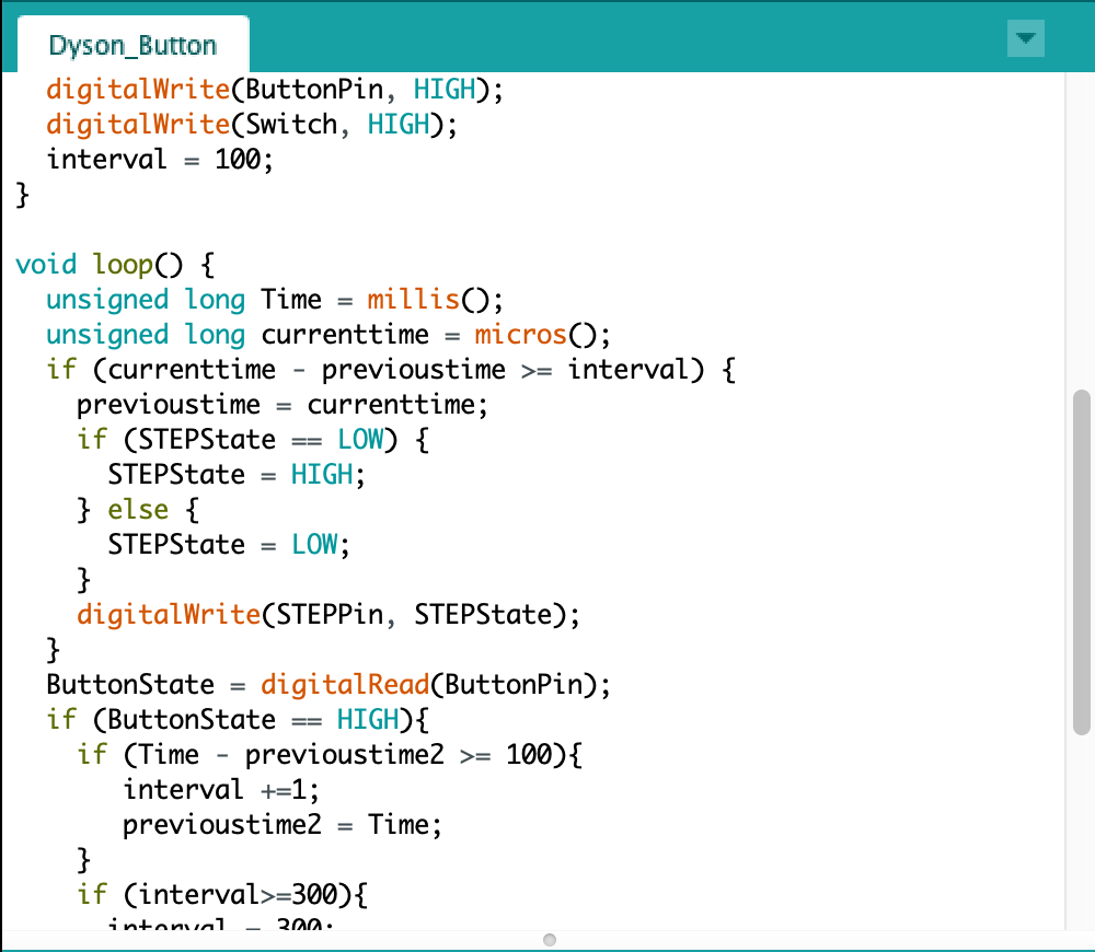
We wrote different codes to direct the motor's motion.
- Switching direction automatically
- Switching direction only when "switch" is turned on ( we designated that low power pin is OFF and high power pin is ON)
Discussions
Become a Hackaday.io Member
Create an account to leave a comment. Already have an account? Log In.