The IR LED / photodiode pair circuitry is simple and is the same found on the ubiquitous line folllowing sensor boards (far right).
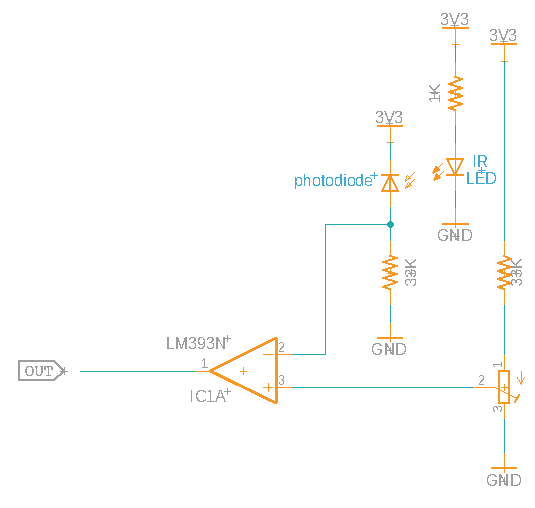
The photodiode (in reverse bias) acts as the upper half of a voltage divider. When exposed to the IR LED, the voltage increases. The other leg of the LM393N comparator input is another voltage divider with a variable potentiometer. Usually used to adjust the sensitivity of the circuit and change reflected distance, it is less needed in this case; the distance between the two diodes is fixed and the diodes face each other thereby removing any IR loss due to the not-perfect-reflective surface.
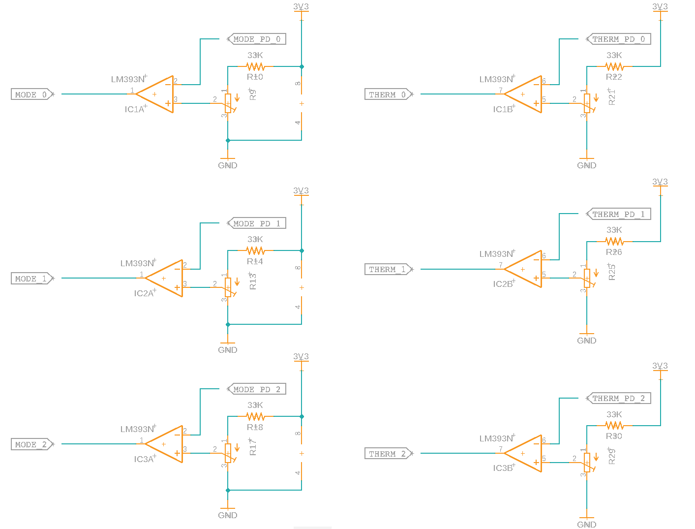
Since this is this board schematic, it doesn't include the IR LEDs and photodiodes as they'll be off-board.
It'd be nice to have the skill (aka patience) to design this as an SMD board but for this project, I'm going to do a through-hole PCB. Three of the dual comparator LM393s will take a fair amount of real estate on the final board; but there isn't a size constraint and the low-volume (there are only three HVAC units in the apartment) won't make the the extra PCB board real estate cost prohibitive.
Discussions
Become a Hackaday.io Member
Create an account to leave a comment. Already have an account? Log In.