 jaromir.sukuba
This device was designed with low power consumption in mind. That’s why I choose operation speed of PIC32 to 4MHz, with peripheral bus clock 2MHz. Running 80MHz PIC32 at 4MHz may seem strange, but this power is quite enough for such as application. Old computers (I mean those with 6502 or Z80 CPU, not your old dual-core system) ran at about the same clock frequency, but it were simple 8-bit architectures, so my system has higher power after all. On the other hand, thanks to using low-power LCD the complete current consumption of MAX32 board with my add-on falls down to 12mA (after unsoldering indication LED from MAX32 board, taking 4mA of current), so this enabled me to run this device for at least ten hours from small 140mAh Li-Ion cell. This also allows using solar cells (practically tested with this one) or small wind generators (untested, but interesting option – for example here) or even water generators (like this one). All those option allows direct powering of this device, but irregularity in power supply can cause open file to be lost. This is reason for powering PP4 from Li-Ion cell and using power from those energy sources for charging this Li-Ion cell, even when PP4 is not turned on.
That is why I created extension for powering PP4 from small Li-Ion battery or solar cell. I measured parameters of this solar cell – the weak February sunlight can make it deliver circa 5,5V at open circuit and 80mA into short circuit, so 0,5W is quite reasonable estimation of its power capabilities. I built a simple circuit:
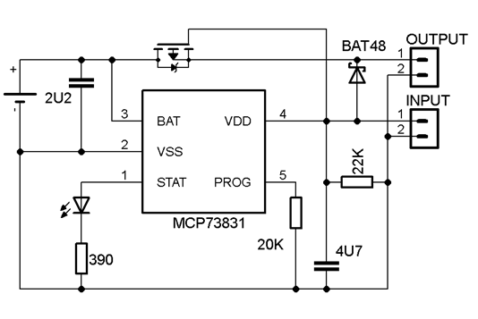
When there is no voltage on input, PFET (Si2333) transistor opens and supplies output from battery. 22K resistor between its G terminal and ground ensures that transistor is fully open.
Input (from solar cell, USB cable or standard 5V wall wart) is brought to output through diode BAT48 and G terminal of PFET, closing D-S channel and removing load from battery. MCP73831 works as Li-Ion charger, charging cell between pins 2 and 3. 20K resistor on pin 5 sets the charging current, on this case it is around 50mA. LED on pin 1 indicates the end of charging process.
There are more sophisticated ways of achieving functionality with both battery and solar power, but this one is simple and usable enough for me.
Discussions
Become a Hackaday.io Member
Create an account to leave a comment. Already have an account? Log In.