 Dan Maloney
I bought a flow sensor from Amazon: https://www.amazon.com/gp/product/B086W73NXN
It's made by Gredia, whatever that means -- I could find exactly zero information on the manufacturer and no data sheets on the sensor. All I knew is what was in the Amazon description - 3/4", brass, Hall effect, up to 30 liters per minute. Brass seemed good because I want this sturdy and safe for drinking water, and 3/4" worked because all the piping in the pump house is 3/4" and I don;t wan to introduce any flow restrictions. One problem: it's only available with British Standard Plumbing (BSP) threads.
I bought adapters that claimed to go from BSP to NPT threads: https://www.amazon.com/gp/product/B07Q6SSTRB. These have bonded washers that are supposed to go over the male BSP threads and form a seal against the sensor when the adapter bottoms out and squashes the bonded washer. But the sensor doesn't have a flat bearing surface for the washer to bear against, so I put an O-ring in the BSP side of the adapter which seal the end of the male BSP spud to the flat surface of the female thread in the adapter. I see that they now have these adapters that basically do the same thing: https://www.amazon.com/GESHATEN-Connector-Adapter-Industrial-Fittings/dp/B089D8NF7H
Next I decided to replace the connector on the sensor with screw terminals. I just added a scrap of perfboard and wired the three leads to screw terminals.
My idea for calibration hit me while I was in the shower -- rig up a scale to weigh water flowing through the flow sensor and count the number of pulses. The weight tells you how much water you have, and you can figure out how many pulses per liter the sensor sends back. My first thought was to use a load cell and an HX711 amplifier to build a digital scale. I worked on that for a few nights before coming to the conclusion that I have a bad load cell -- I could never get a stable reading. Then it dawned on me that I cold build a much, MUCH simpler calibration rig:
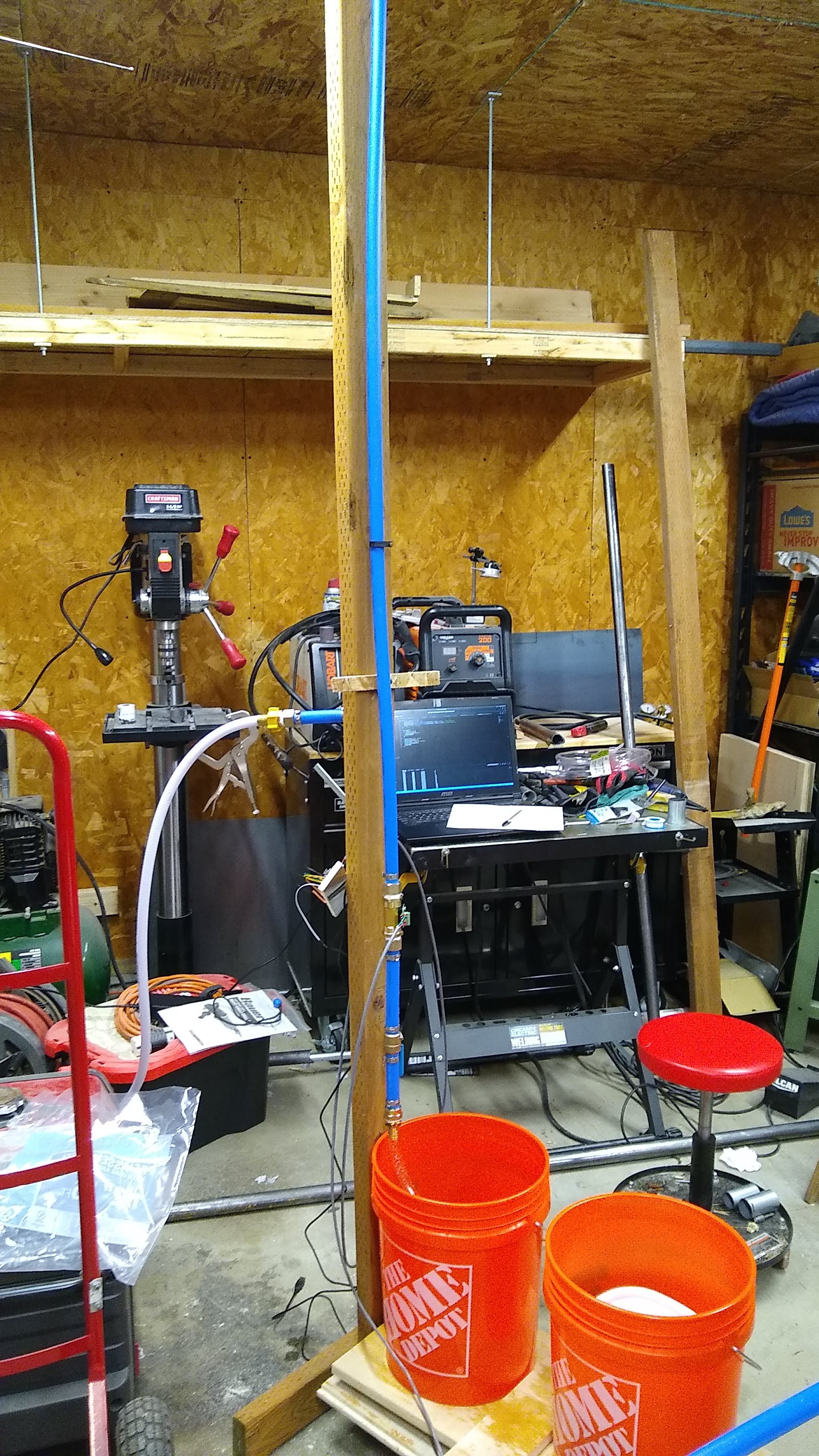
It's a little hard to see what's going on, so I'll explain. The blue pipe is 3/4" PEX, and the brass bit near the lower end of the pipe is the flow meter, followed by a quarter-turn valve. I made the pipe above the flow sensor long and vertical so that the flow through the sensor would be as close to laminar as possible. Water feeds into the calibrator through the white hose on the back of the upright.
The two buckets on the board are a crude balance. The back bucket catches the water coming out of the flow sensor, while the other bucket has either a 1-kg or 5-kg weight in it. There's a piece of conduit under the board to act a a fulcrum, and a switch under the teeter-totter:
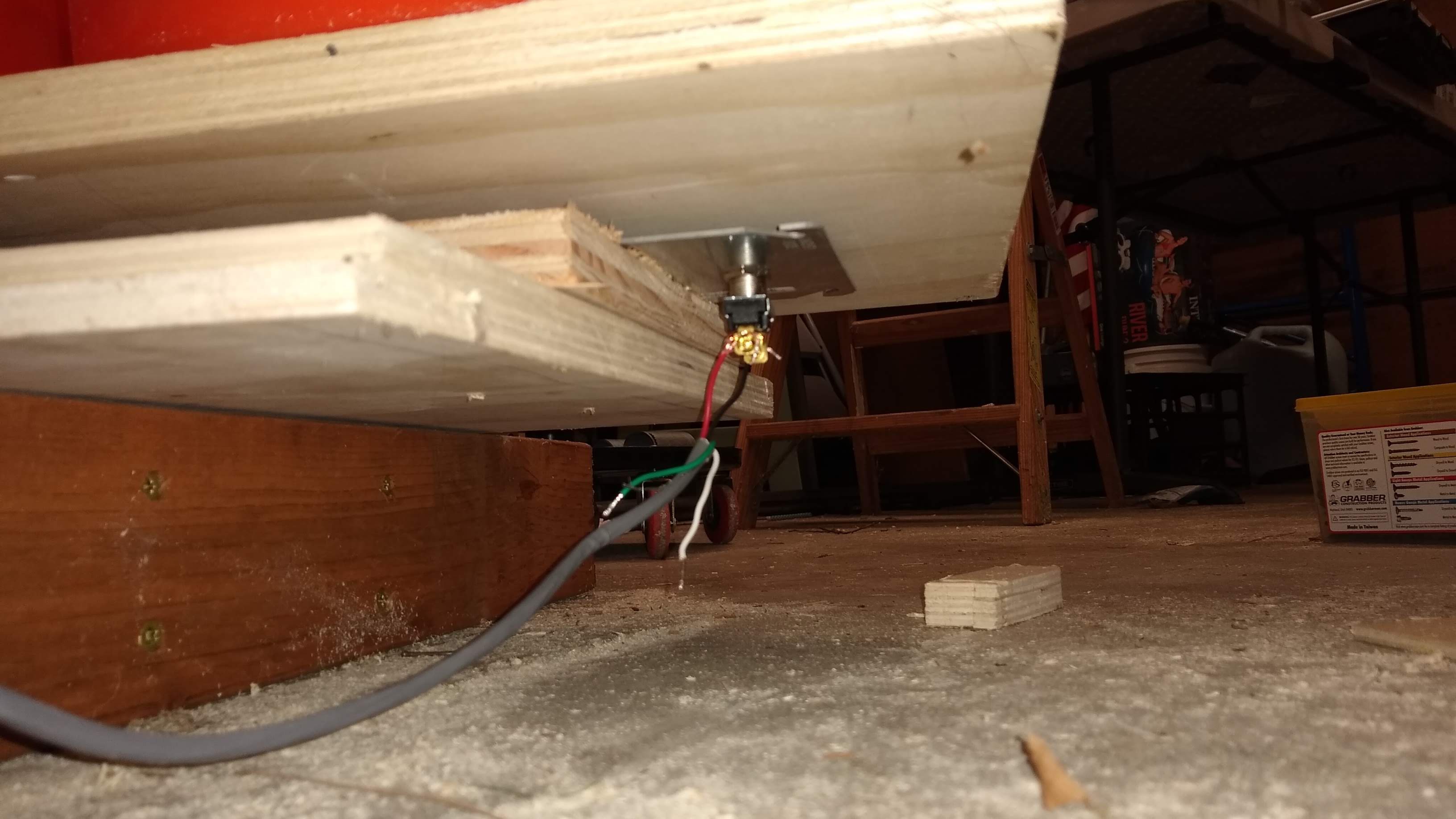
The switch stays closed until there's enough water in the first bucket to tip the balance. My code starts counting pulses from the flow sensor and waits for the input connected tot he switch to change state. When it does, it stops looping and displays the number of pulses. Here's the code:
#include <Arduino.h>


volatile int pulses; // Measures flow sensor pulses
unsigned char flowsensor = 12; // Sensor Input
unsigned char limitsensor = 14;
volatile bool flag = false;

ICACHE_RAM_ATTR void flow () // Interrupt function
{
   pulses++;
}

ICACHE_RAM_ATTR void limit () // Interrupt function
{
   flag = true;
}


void setup() {

   pinMode(flowsensor, INPUT);
   pinMode(limitsensor, INPUT);
   digitalWrite(flowsensor, HIGH); // Optional Internal Pull-Up
   digitalWrite(limitsensor, HIGH);
   Serial.begin(115200);
   Serial.println("Starting...");
   attachInterrupt(digitalPinToInterrupt(flowsensor), flow, RISING); // Setup Interrupt
   attachInterrupt(digitalPinToInterrupt(limitsensor), limit, RISING); // Setup Interrupt
   sei(); // Enable interrupts
}

void loop() {
  if (flag == true) {
    Serial.println("Done");
    delay(100000);
  }

  Serial.print("time: \t\t");
  Serial.print(millis());
  Serial.print("\t\tpulses: \t\t");
  Serial.println(pulses);
  delay(100);
}
I used a Wemos D1 Mini because I had one handy, and because I managed to fry one Nano and find another that won't output anything to serial.
I did a bunch of runs and here's the data:
| volume | start | end | elapsed | pulses | ppl |
| 1 | 2768 | 5873 | 3.105 | 447 | 447.0 |
| 1 | 3796 | 6673 | 2.877 | 407 | 407.0 |
| 1 | 2771 | 6376 | 3.605 | 524 | 524.0 |
| 1 | 2670 | 5174 | 2.504 | 376 | 376.0 |
| 1 | 2970 | 6074 | 3.104 | 460 | 460.0 |
| 5 | 3270 | 22000 | 18.73 | 2488 | 497.6 |
| 5 | 2969 | 21599 | 18.63 | 2240 | 448.0 |
| 5 | 2968 | 19897 | 16.929 | 2138 | 427.6 |
| 5 | 1366 | 18197 | 16.831 | 2195 | 439.0 |
| 5 | 2569 | 19597 | 17.028 | 2205 | 441.0 |
| 5 | 3100 | 20699 | 17.599 | 2256 | 451.2 |
| 5 | 3170 | 18395 | 15.225 | 2238 | 447.6 |
| 5 | 4273 | 18696 | 14.423 | 2185 | 437.0 |
| 5 | 6376 | 19798 | 13.422 | 2039 | 407.8 |
| 5 | 2667 | 16750 | 14.083 | 2126 | 425.2 |
Start, end , and elapsed are just the number of milliseconds -- no real reason to keep track of them, just did it for the heck of it. The numbers were pretty tight -- averaged 442.4 pulses per liter. I think I'll use 442 pulses as my constant. For gallons -- I don't mind calibrating in liters, but gallons is more useful to me in production -- it'll be 1,674.66 pulses. I'll probably use 167.5 pulses and keep track of flow in tenths of a gallon.
Discussions
Become a Hackaday.io Member
Create an account to leave a comment. Already have an account? Log In.