 Julian Calaby
When I initially built this, I mapped out the matrix of the USB keyboard controller by attaching wires to the pads for the 8 rows and 18 columns to a bunch of switches and used those to map out the entire matrix.
I did this by building a piece of protoboard with 26 switches all wired to a common wire, then wiring the rows to 8 and the columns to the remaining 18. I could then simulate a key at a particula row and column by pressing the switches for the row and column simultaneously.
I wrote this up in an Excel spreadsheet which I've lost somewhere on one of the dead hard disks from my first computer.
I then cut traces and soldered wires to convert the matrix of the AEK into that particular matrix.
Now, 15 years later, I'm having to reverse-engineer the bits I need from that map by beeping out the keyboard.
I ended up with this:
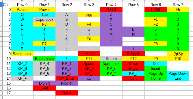
(Colours indicate rows of physical keys, blank cells are rows and columns that don't have a corresponding key.)
I'm going to need to make some modifications to improve this to make the microcontroller selection a touch easier:
- Combine columns 9 and 15: this moves the shift keys into the gap in column 9.
- Combine columns 14 and 16: this moves the left alt key into a gap in column 14.
- Combine columns 0 and 17: this moves the right alt key into a gap in column 0.
This leaves me with 8 rows and 15 columns requiring a total of 23 GPIOs to produce a total of 105 keys. Adding in the three LEDs, I need 26 GPIOs.
Frustratingly my LeoStick has only the Arduino standard 14 + 6 = 20 GPIOs and even if I use the 3 in the programming port, I'm still 3 GPIOs short, so I'm going to have to buy a microcontroller for this.
Discussions
Become a Hackaday.io Member
Create an account to leave a comment. Already have an account? Log In.