 David Tucker
I decided to square up and tram my system in preparation to making a replaceable waste board that is easy to swap out and that has been surfaced.
The first step is simple enough. To square the Y axis to the X axis we just cut a pair of squares out of some material, then flip one over along the X axis and check if the Y axis diverges from each other. Or if you don't want to waste any materials you can just draw a square on two pieces of paper, then flip one over and hold them up to the light to see if the squares line up. If there is any divergence then dial the Y end stops in/out as needed and repeat the measurements.
The next step is more tricky. To tram up the spindle we need to first work up a parallels surface to square against. An easy way to do this is to place a sheet of glass on top of the bed, then using a dial indicator we can run it back and forth over the glass to find the low spots then shim them up till we have as flat a surface as we can manage.
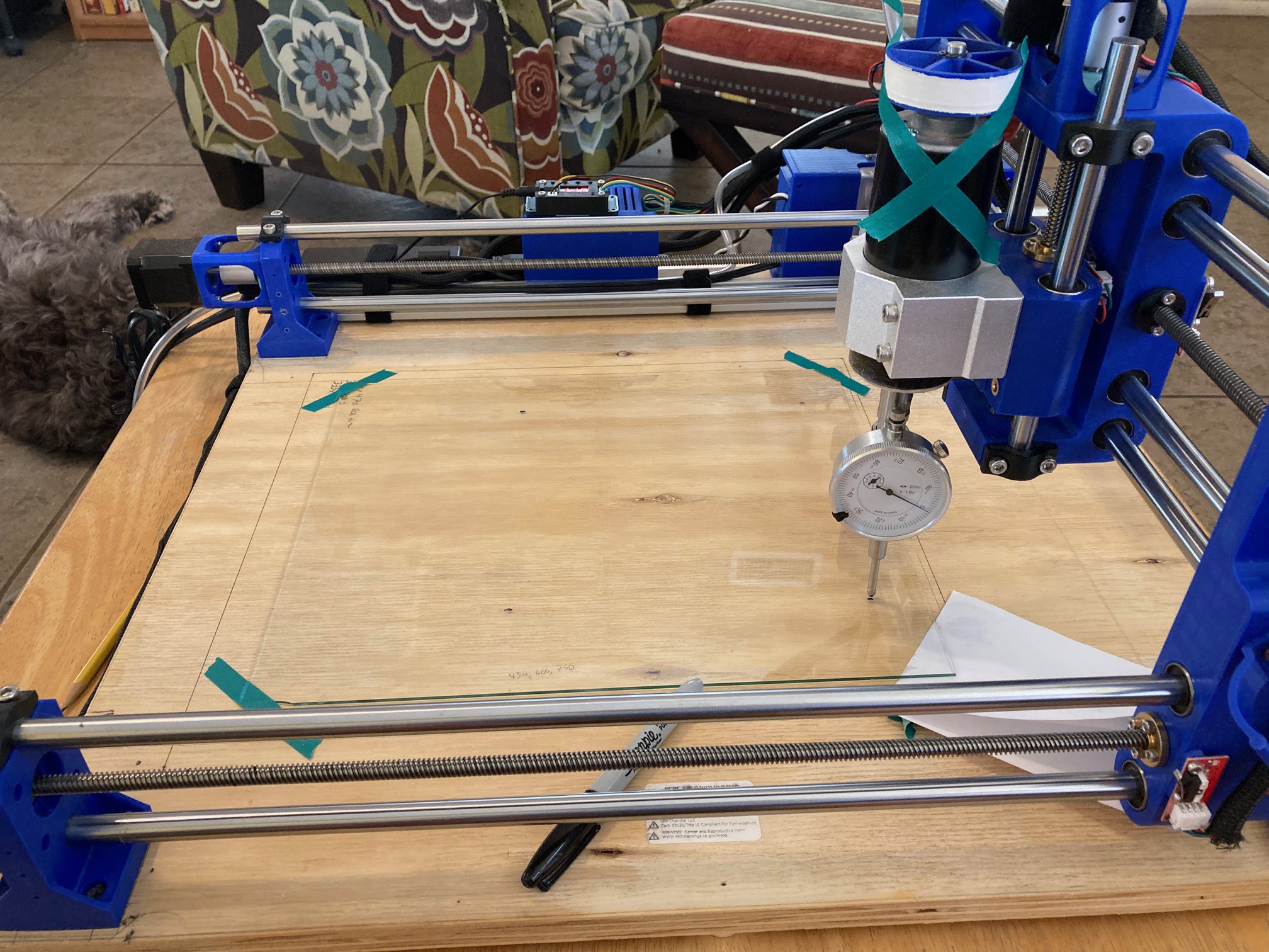
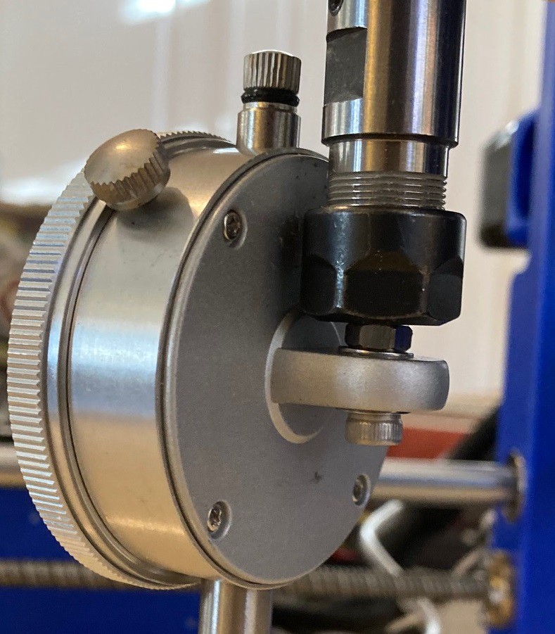
To secure the dial indicator to the spindle I took the back off and rotated it 90 degrees then fixed a bolt through the hole on the back and then chucked the bolt into the spindle collet. I also taped the spindle up so it could not rotate, that helps keep the measurements more consistent as you move the spindle over the glass.
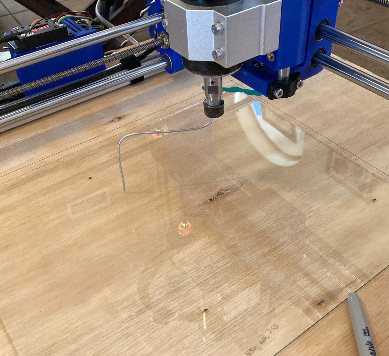
Once the glass is level then I chucked a piece of bent wire into the spindle, jogged the spindle to the center of my glass, then lowered it to the point where the wire was just about to touch the glass at the highest point. Then by spinning the wire around I could see how much out of true the spindle is in both the X and Y axis. To true things up in the Y axis (called nod, as in nodding your head yes) I placed a small piece of aluminum tape on the top or bottom of the spindle holder as needed to pitch the spindle forward or back. Repeat the process as needed till you have it square.
For the Y axis things are trickier. I have made the machine very symmetrical so it should be fairly true, however to correct for tilt (as in tilting your head side to side) it is easiest to loosen the spindle a bit, then twist the motor and mount in the direction you need before tightening it all back up again. It is not perfect but it can bring thins closer to true.
I measured about 1 mm of tilt in the Y axis using a 100 mm long wire (200 mm in total from side to side), Using a 20 mm blade to level my spoiler board with 30% stepover then should give me less than 0.05 mm of error along the Y axis. Hopefully that is close to invisible.
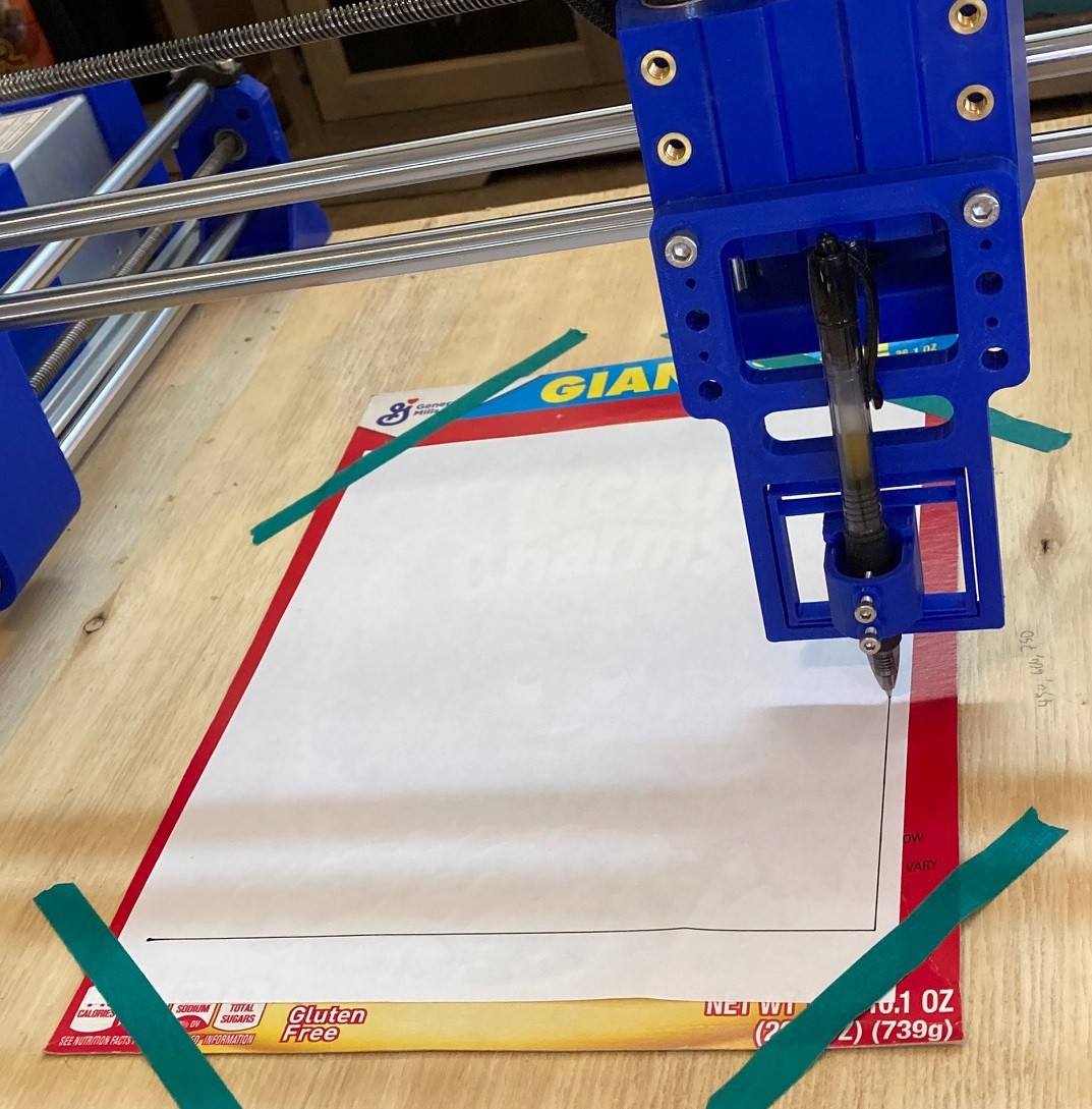
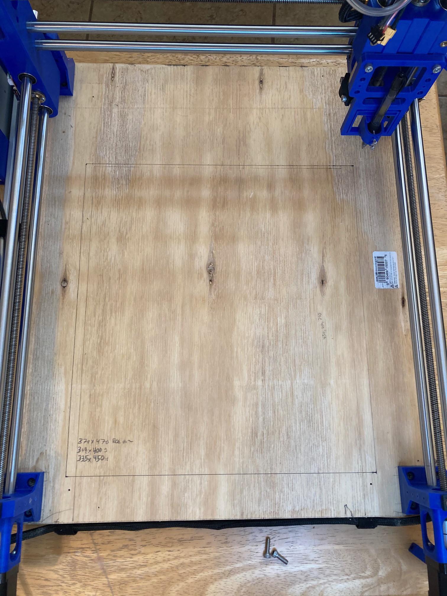
Now I need to plan out how big to make my spoiler board and how to mount it. For starters I loaded up my pen and jogged the machine to the extent of motion. This is not perfect because different attachments protrude different amounts in the X and Y directions, but it helps me get a rough idea of where to place the board. Tomorrow I will try to finalize the plans and come up with a way to get my machine to route holes in everything.
It is a bit hard to see the lines but if you look closely you can see that there is a good amount of space at the rear of the machine that is wasted. Fortunately it is not lost, it just shifts forward. But the bit does extend a ways past the front of the base of the machine when jogged all the way forward. Someday I will need to rethink things and add in a raked Y gantry holder to bring the spindle further back. This may help stiffen up the machine a bit as well since the weight will be more evenly distributed.
This guide by Roger Secura was a help in working out how this all works.
Discussions
Become a Hackaday.io Member
Create an account to leave a comment. Already have an account? Log In.