 David Tucker
I have eluded to it before but never talked about the different types of rotary axis we can implement. There are three choices, two of which are a better fit for our system.
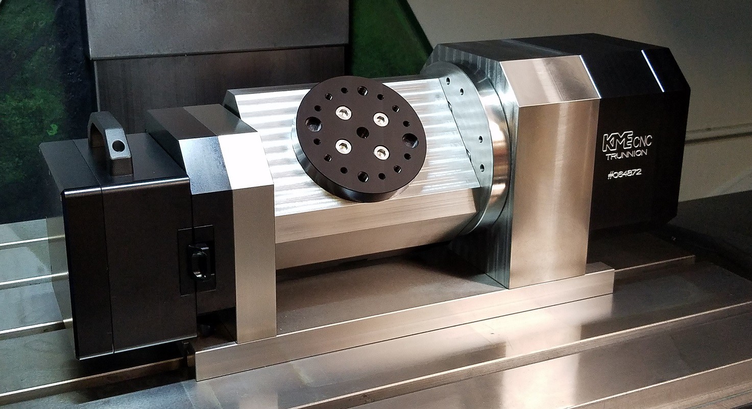
The first option is a 5 axis trunnion table. This is basically a rotary axis that can be tilted and the big advantage over a rotary axis is that you can cut pockets at most any angle to the base of the part. Think of machining the top end of a v8 engine block in one programming step.
The down side here is that it requires 5 stepper drivers at a minimum to work (6 if we want to keep using an auto squaring x axis and keep the y axis in play). The other issue is that it needs a lot more vertical working height than we have to give.
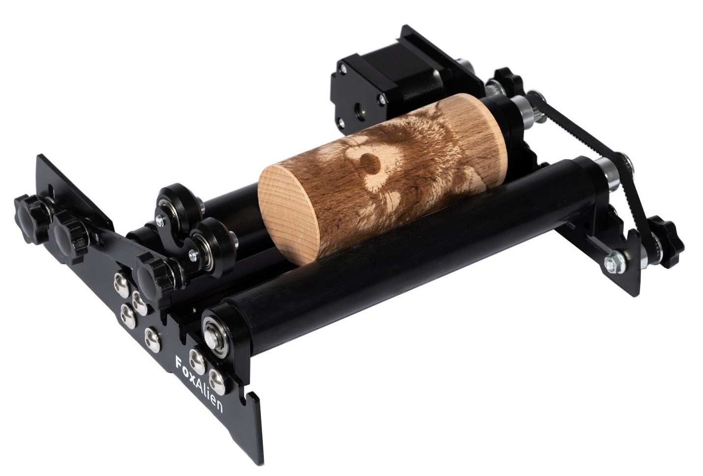
The next option is some sort of a roller system. These can be long rollers or individual wheels that can be positioned at key places under the part. If the part has some sort of taper to it you can add a second set of idler wheels to prop up the narrow end of the part on so the face is parallel to the laser or tool.
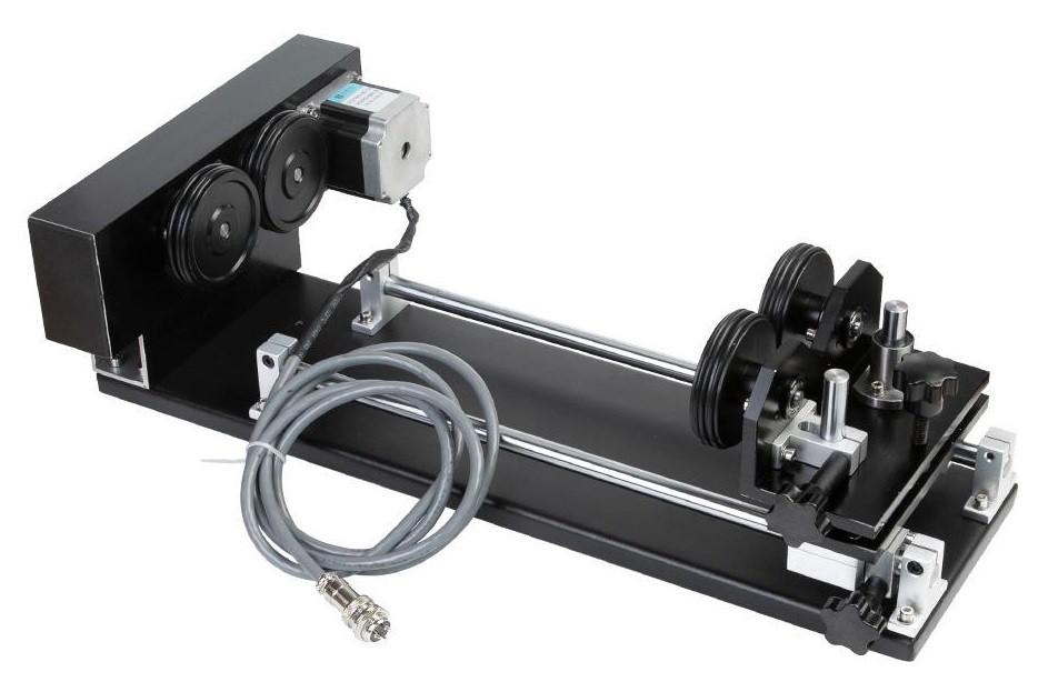
The upside here is simplicity and ease of setup, and in certain cases the ability to handle longer objects.
On the downside the part is only held in place by friction so a light weight part may need weights added to it to make it work, and there is always the chance of the part slipping so you are more or less restricted to raster images where the part only makes one single rotation while being etched. Also this is basically limited to laser etching since it is the only tool that does not touch the part.
This setup is driven by the circumference of the part. That is rotating the stepper by a fixed amount will always move the outer surface of the part a fixed amount, regardless of the diameter of the part. i.e. moving the motor 10 degrees may move the surface of the part 5 mm for a 10 or 80 mm diameter part.
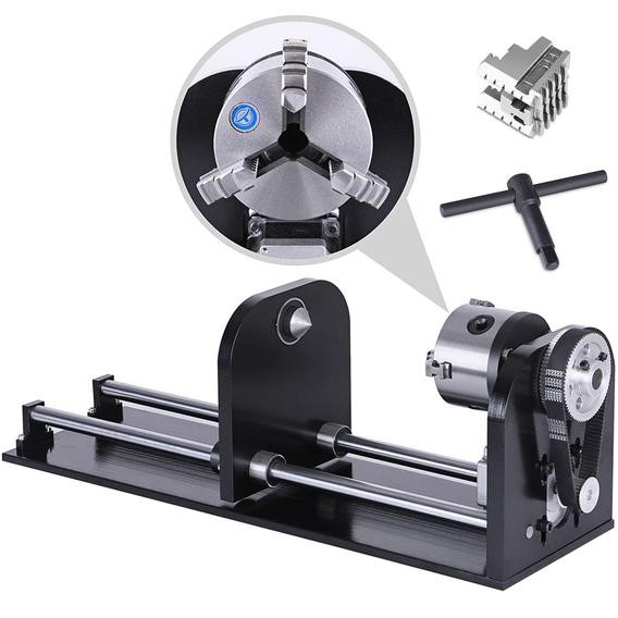
The last option is using a chuck or other hub with an optional tail stock to help support the part. The piece is clamped in the chuck or bolted directly to the hub in some fashion.
The upside here is that the part is very well clamped so it can't slip. That allows us to move the part back and forth with a high level of precision and it allows us to use various cutters to carve away the material in addition to using a laser.
On the downside it is more complicated to deal with tapered parts. You either need to tilt the chuck or tilt the whole mechanism. This is doable but it is not as simple as sliding some wheels around. Also if you want to cut really long parts you need some sort of additional support or you have to give up on the tail stock and only support the part from one end.
This setup is driven by angular position. That is rotating the stepper motor a certain amount will rotate the part through a set angle regardless of the diameter of the part i.e. rotating the stepper 10 degrees may rotate the part 1 degree for a 10 or 80 mm diameter part.
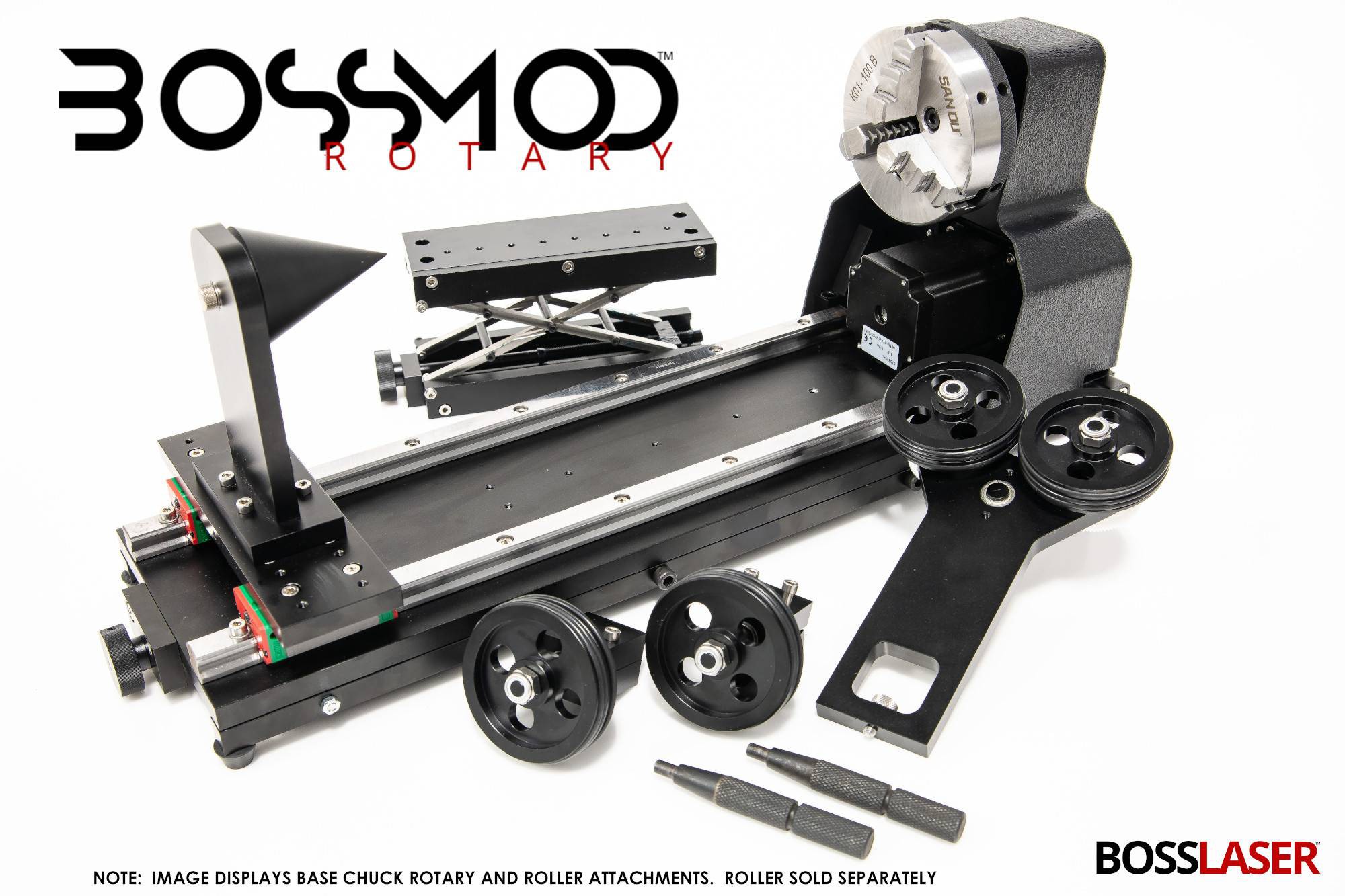
It is also possible to make a setup that combines both rollers and a chuck into the same jig.
I think for our needs a chuck type setup is the best. Rollers may be simpler to design but they can't be used with the mill and since we have such a small working z height we really need a setup that allows us to use the full vertical range.
Discussions
Become a Hackaday.io Member
Create an account to leave a comment. Already have an account? Log In.