 Paul Stoffregen
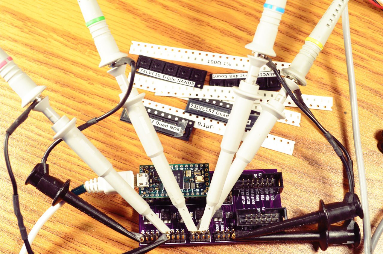
Built up 1 of the boards and connected it to my scope for a first look at the waveforms.
Here's the big picture view, of the entire 256 bit TDM frame. Or two of them, plus edges of 2 more, so ~600 bit times shown here. Thanks to the scope's frequency counter you can see the yellow frame sync pulse is happening at 44.1 kHz. So this view is the time of 2 audio samples, and of course the goal is to pack 16 sets of 16 bit data originating from 2 different CS42448 chips into those 256 bit times!
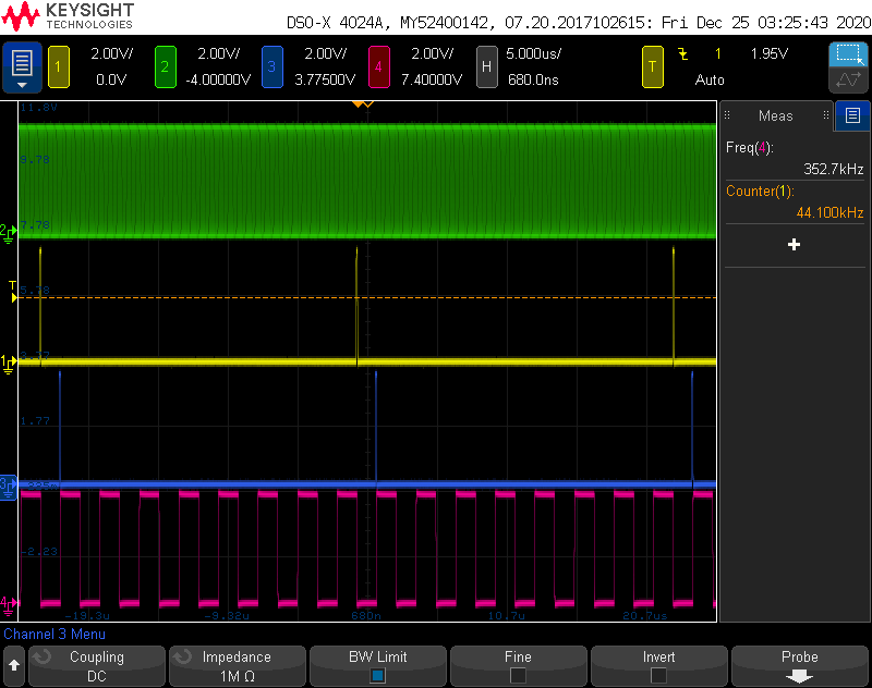
The green and yellow traces are the bit clock and frame sync generated by Teensy 4.0.
Blue is the 16 clock delayed frame sync intended for the 2nd CS42448 chip. Red is the 2:1 mux control signal, which will select which CS42448 chip talks to the Teensy TDM data pins.
Just to recap... the idea is the 2 CS42448 chips are running from the same bit clock, but one is 16 cycles delayed. CS42448 uses 32 bit data, but the low 8 bits are always zero and the next 8 are pretty much always just noise. So the mux routes each chip's 16 most significant (and only worthwhile) bits to Teensy 4 while the other chips (worthless) 16 least significant bits are discarded.
But upon zooming in, I saw something I probably should have considered, but didn't think about until now....
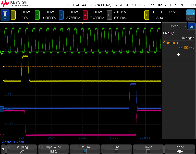
We might have a problem with setup or hold time. Maybe. Here's a view with the bit clock positioned between the 2 frame sync signals, so it's easier to see.
Teensy 4.0 is generating the frame sync pulse on the falling edge of the clock. The CS42448 uses it on the rising edge. So this way gives the best possible timing margin, it's valid half a cycle before needed and remains stable for another half a cycle.
But my little logic circuit is updating it outputs on the rising edge. So a big question is whether the CS42448 needs the signal to remain stable for a hold time after the rising edge?
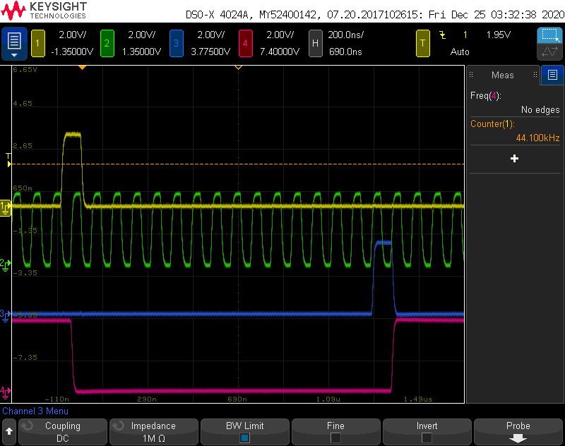
Here's an intense zoom in...

Looks like frame sync (blue) stays valid about 5 ns after the clock edge (green). The mux control changes about 2.5 ns after the clock, but maybe that's ok since the logic inside the mux chip will add a little more delay to the data signal.
In hindsight, maybe I should have used 2 more flip-flops to retime the control signals onto the falling edges?
Discussions
Become a Hackaday.io Member
Create an account to leave a comment. Already have an account? Log In.