 Ted
TedThe rough plan:
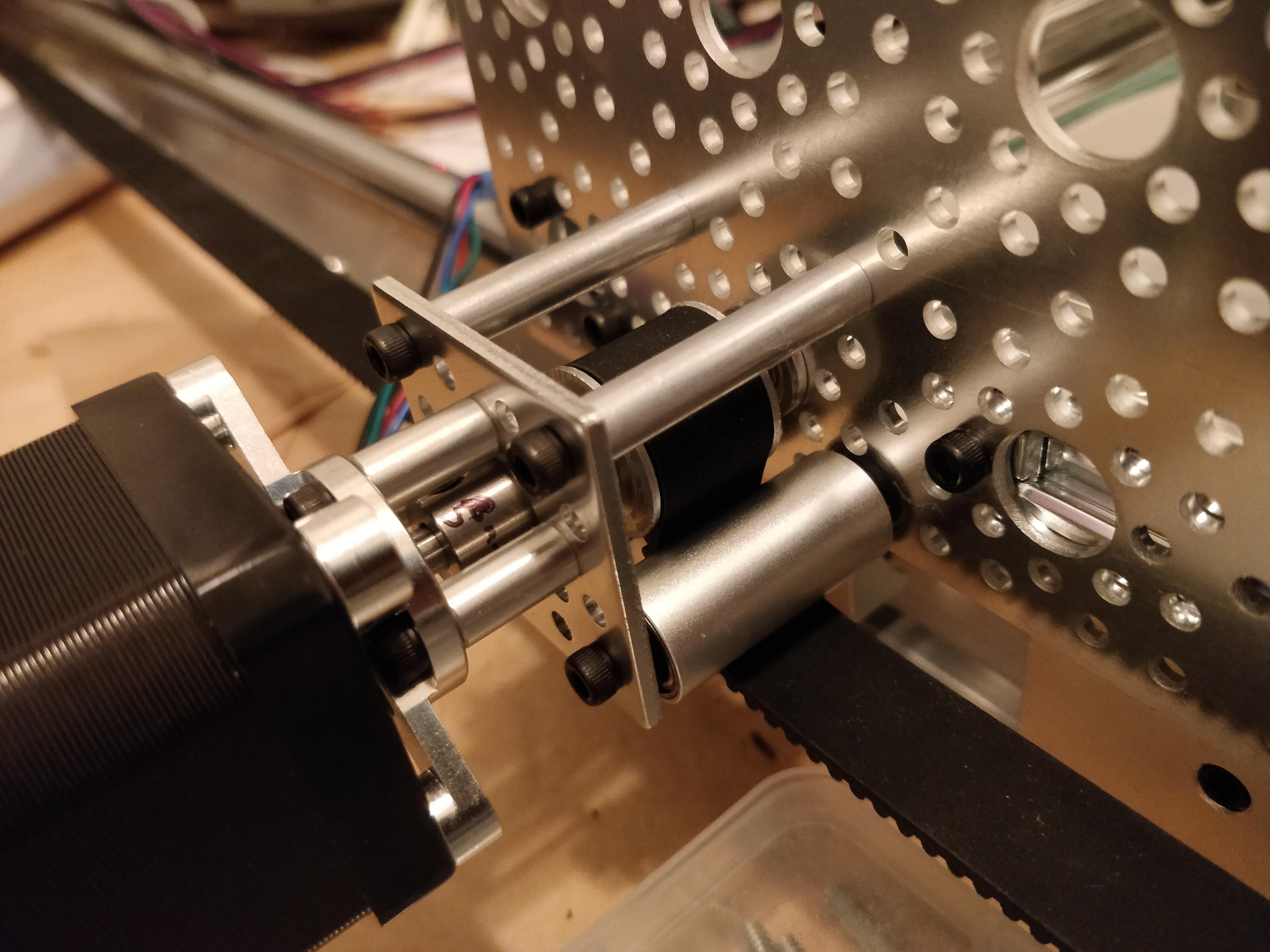
(ignore unattached Y bearings - it was just testing alignment)
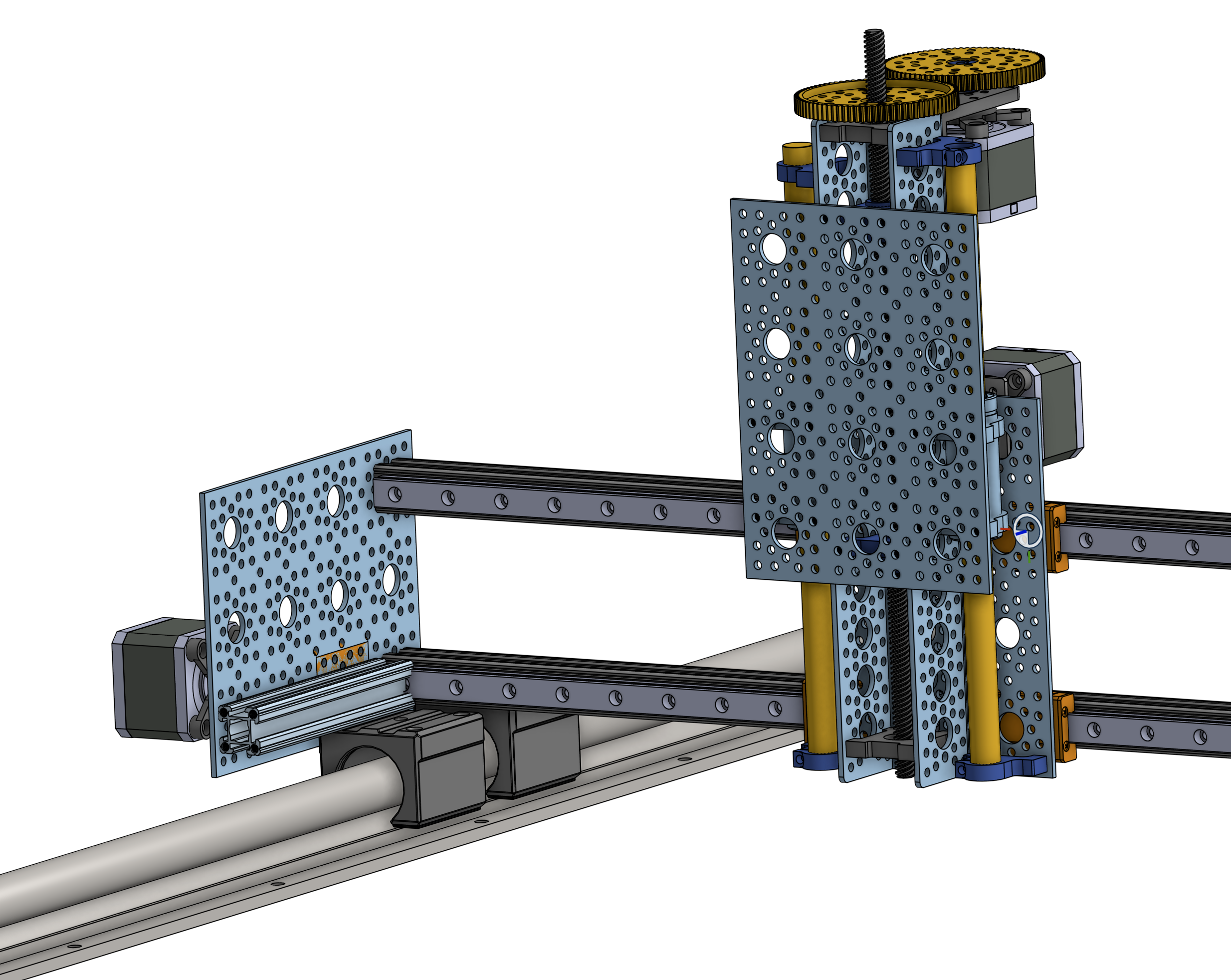
The design is pretty simple, though it has one variation from most other designs I see. I didn't like the idea of the stepper's shaft handling all the load from the X&Y belts while supported on only one end. That seems like a recipe for a bent shaft and/or the belt jumping. So instead, the shaft for the bely pulleys are supported on both sides:
I'm using HTD 3mm belts - 3mm pitch GT2 would be more appropriate for lower backlash, but this is what Gobilda had parts for. Popularly available 2mm GT2 belts seemed like they might be too prone to skip under load.
Most of the parts were ordered during ServoCity Cyber Monday Sale, which made a ~25% reduction in cost for this project. I also bought some very under-priced SBR20 rails for the Y-axis on Amazon and reasonably priced MGN12 rails on Banggood for X-axis. The MGN12 rails are still the mail despite "ships from US" claims.
So, instead for the X-Axis I used Actobotics V-Wheels + a 12mm rod w/ linear bearings. (I only had one v-wheel set and one long enough rod) I suspected the Actobotics "X-Rail" (~2020 extrusion) would have too much give for a 2' (~600mm) span. It does have too much give for what I plan, so may wait for the MGN12 rails before trying to push it.
v0
Initial assembly I skipped the Z-axis shafts + bearings, and left only the lead screw + channel. I had an idea to use some springs and a screw to let the pen move upward in Z to account for an uneven surface / nonsquare bed, as seen here:
It worked, but very poorly - there was too much friction with the screw threads and too much wobble, so I added the Z-shafts...and it wouldn't move at all. It turns out order of tightening screws is very important. I tightened the shafts to the center channel first and then attached the parts to the linear bearings. Instead I had to loosen the screws on the connectors center column, then move the carriage to the bottom; tighten the bottom screws; move carriage to the top; tighten the top screws. Then tighten then screws on the carriage itself. Finally the Z-axis moved fairly freely. But there was still enough friction that the pen wouldn't drop with gravity. So, I added some springs. (The Z-screw is not directly connected to the carriage)
success!
There looks like ~0.5mm or so backlash. It's because the pen pressure is too high and the angle of the pen itself isn't rigid enough, not due to the belts. Less pen pressure yields better results. Ideally I'd just use gravity, and may someday improve it to not use springs. But being a plotter isn't the only plan for this.
Discussions
Become a Hackaday.io Member
Create an account to leave a comment. Already have an account? Log In.