 doctek
The uploading clip, mentioned in the Details section above, is slightly modified from the original. Following is a description of the version used for tArmDuino, how it's assembled, and how it's connected to the ST-Link.
The circuit board and connector are unchanged. The KiCAD files have been placed in the Files section and include the gerbers and the solder paste stencil. Here is the board with the contactor in place.
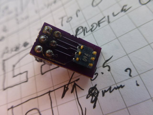
The spacer or frame around the contactor is also modified compared to the original version. It now has locating tabs on two sides and is designed to fit tArmDuino. The stl version is in the Files section. After printing, it should be adjusted to 1.75 +/- 0.05mm thick. It's purpose is to keep the contactors from being crushed beyond their elastic limits, while still allowing them to make firm contact with the pads on the tArmDuino.
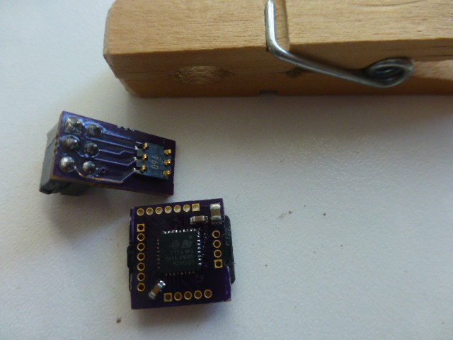
This shows the board with the contactor, and the tArmDuino in place on the frame.
Here is the frame in place on the contactor. Note the orientation of the tARmDuino. Obviously, it gets flipped over to mate with the contactor, but note the alignment of the lettering.
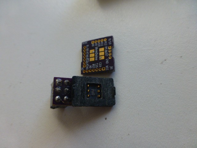
Shown here is the frame on the tArmDuino contact pads. Again, note the position of the lettering.
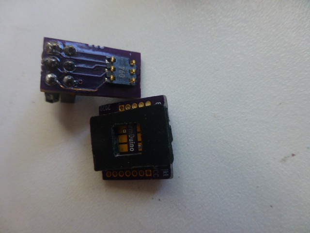
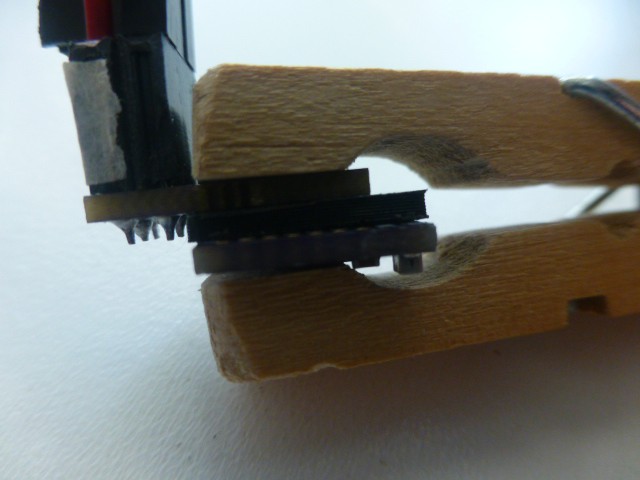
This is the stack up of the contactor, frame, and tArmDuino. The clothes pin is just used as a support here.
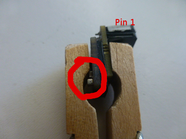
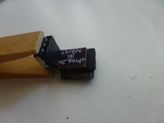
To hold the programming connector in place, an ordinary clothes pin is used. It is slightly modified using a file or rasp to make it fit securely and hold the connector squarely against the board. The pictures show the idea pretty clearly. Here it is shown in place. The white tape I placed on the wiring plug indicates pin 1, and the circle emphasizes the position of the two capacitors in the corner of tArmDuino (one larger than the other). These serve as a useful reference for correct orientation of the clip.
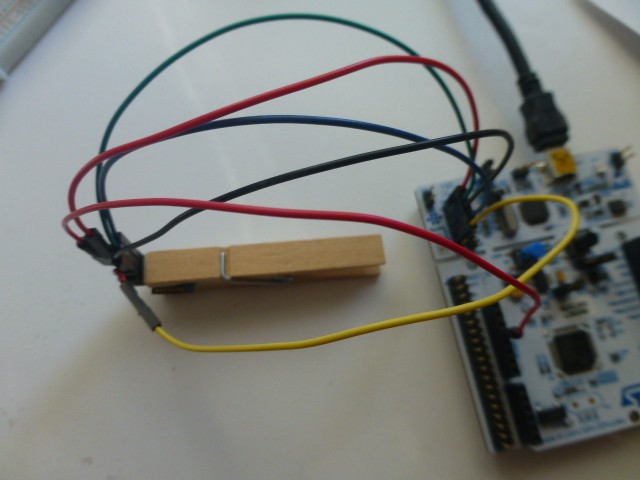
Here is the wiring to the ST-Link. Note that the pin names of the pins on the programming clip are changed for programming the tArmDuino. Pin 1 is nRst, 2 is Gnd, 3 is Vcc, 4 is SWC, 5 is Gnd, 6 is SWD. There is no need to connect both grounds, pick your favorite. Note that Vcc to the ST-Link must be connected as well to the 3.3V powering the tArmDuino (from the 3.3V power connector on the Nucleo, possibly).
I used the Blink demo program (from Arduino/File/Examples/Basics) as discussed in the "tArmDuino Programming and Debug" build log above, changing led to 7 (PA8). The sketch was uploaded to the tArmDuino breadboard version, labeled "Small ARM 32", to make sure it worked. Not surprisingly, it worked! Then I wired up the debug clip as shown above and clipped it to the tArmDuino tiny version and uploaded to it. It works as expected. The tArmDuino is fully ready for whatever projects I can come up with!
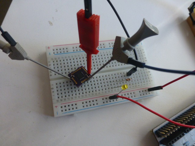
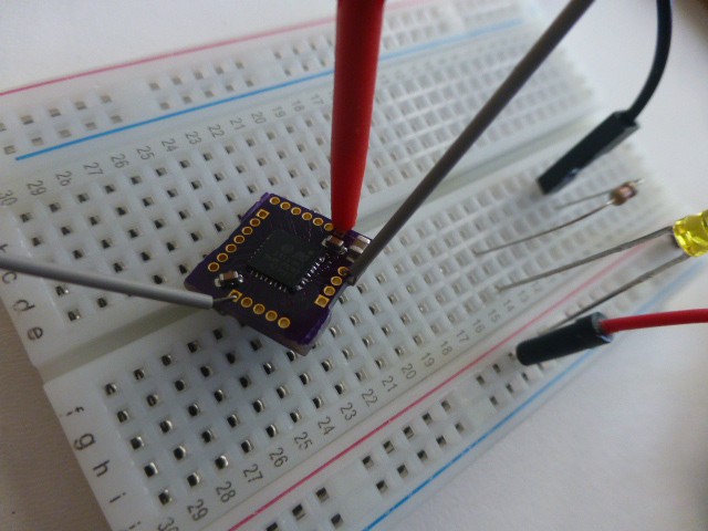
These pictures show the tArmDuino hooked up to blink a led on a breadboard.
Since the ST-Link is used to upload tArmDuino, it clearly could be used with gdb for debugging if needed. I personally prefer to debug using the Small ARM 32 (breadboard) version, then uploading to the tArmDuino, but there are times when it makes sense to debug directly on the tArmDuinon. This works fine, but sometimes any wires soldered to it can get in the way.
Discussions
Become a Hackaday.io Member
Create an account to leave a comment. Already have an account? Log In.