 John Duffy
Parts came in, assembled and got the major pieces of the analog front end working together.
This is the input attenuator that allows higher voltages to be measured (up to ~200V right now, but easy to change the ranging), the PGA for measuring smaller voltages (gain is up to x32) and main ADC. Took forever to get the ADC working, spent pretty much all of yesterday working on it but finally got it just now, the switches and PGA only took about an hour to add after that. So at this point, it's got three high ranges (1.5V, 15V and 220V max), and 7 lower ranges. Low (mV) ranges are just gain settings in the PGA, theoretical minimum resolution is about 3uV, but I doubt that will be usable in practice. Shooting for about 0.1mV resolution, but this is still proof of concept so not going to be too worried about it.
The parts I'm using for the ADC is an MCP3461R (16b ADC, up to 1Msps at lower resolution), PGA is an MCP6S28, and the switches are NL7WB66's. Annoyingly I picked out those switches over two years ago for their extremely low off-leakage (typically ~1nA!) which is hard to find, and between ordering them and receiving them, they went last-time buy on Digikey. This ended up being the single hardest part to find, and now I'll have to replace it for any future version. Dang it. Any case I've got a bunch of them on hand and will get through prototyping with this, before I start worrying about a replacement.
If anyone else happens to be using the MCP3461 (or MCP3462 or MCP3464 ), for some weird reason, even if you're not using it, the IRQ pin has to be pulled high. Something internal to the device requires this pin to change state to allow the ADC register to be read. AND this is not stated until of the pin description on page 31 of the datasheet (exactly where one WOULDN'T look if they're not using that pin! Why ONLY there?! </rant>
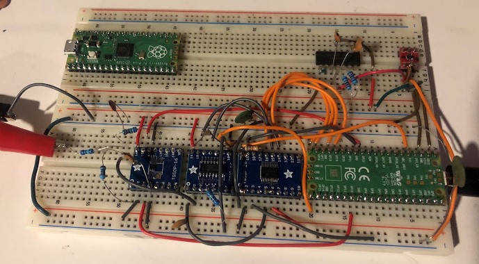
AFE on a breadboard - far left clips are voltage coming off my power supply to measure, the blue resistors are the input attenuation resistors, the first breakout board is for the switches, middle is the PGA, right is the ADC. A pi Pico is running the show on the right. Top right red board is a separate 3.3V linear reg for the analog supply, and finally the DIP IC with some caps and resistors to the left of that is just an LM324 opamp to split the rail for analog ground (which sits at 1.65V relative to digital ground).
I haven't added the protections, compensation caps or measured the analog bandwidth of this yet, I expect that will actually be fairly annoying since all the parasitics will come out to play. I do plan to have this usable up to a few KHz, should allow for decent peak detection and true RMS calculation, both of which I want to implement at some point.
Discussions
Become a Hackaday.io Member
Create an account to leave a comment. Already have an account? Log In.