How it started:
I have wanted to improve my latest project, which was a reflective microscope from a CD player head optic. That design was not so great because of the poor optical and mechanical implementation I did. My main gool was to get better image quality and usability with some extra options, what I will detail later.
Improvements:
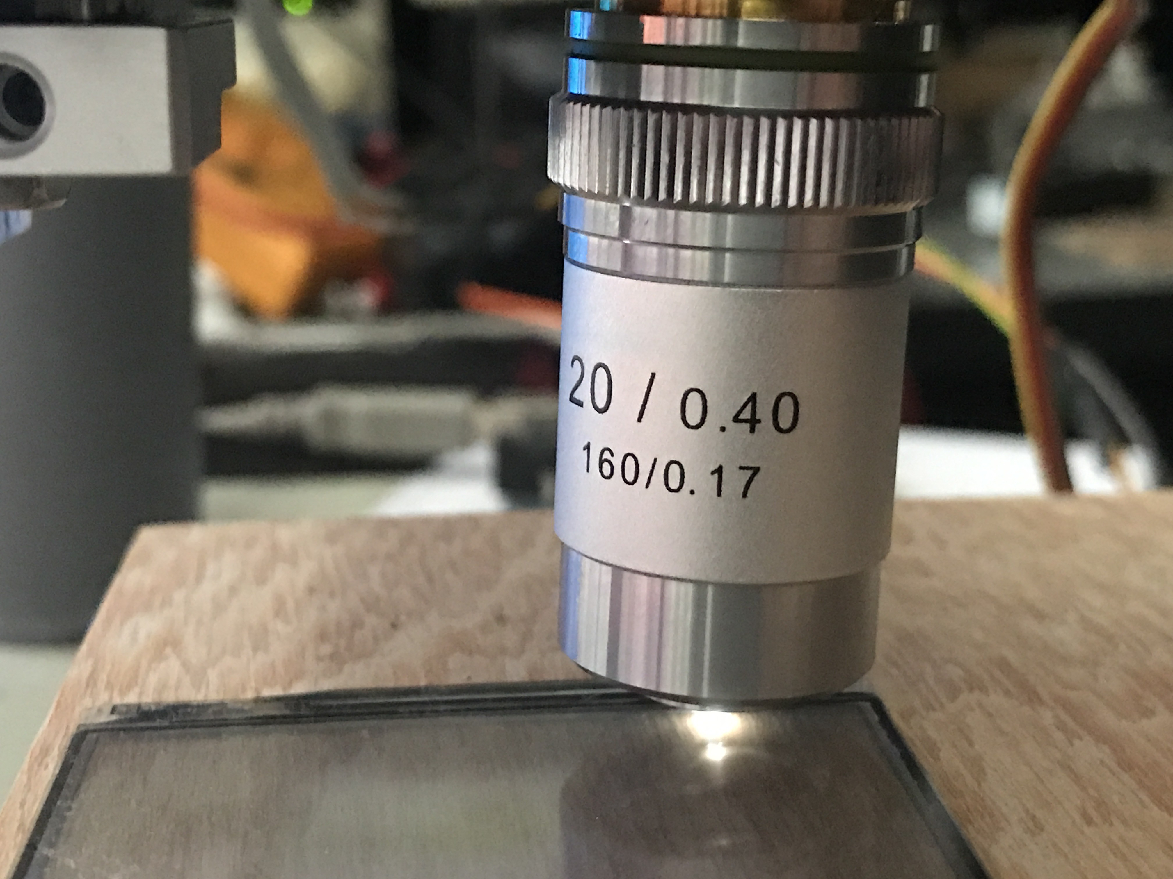
First I have decided to get a proper objective, which will highly improve the image quality. I have made calculations and ended up with a relatively cheap 20X Semi Plan objective. With this I have got around 100um x 100um Field Of View (FOV).
My second investment went into a 3D Printer, what I have wanted a really long time for my home lab. The 3D Printer got me freedom. With it, I could design anything in CAD and it can make it for me.
Basic design:
For a reflective microscope we only need a few parts like:
- Objective
- Beam Splitter
- Light source (In my case a white LED)
- Camera (for capturing the image)
With these requirements I made a simly diagram how it shoud look:
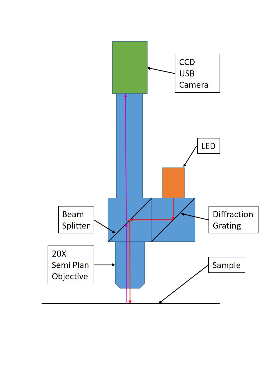
On the above diagram I marked the light path with arrows, dispite of the diffraction grating it is a basic reflective microscope. For now just consider the grating as a mirror, later on I will describe what it does.
All the mechanical parts I have 3D printed, was designed in Fusion 360. You can find all of the designed mechanical parts here: https://www.thingiverse.com/thing:4703960
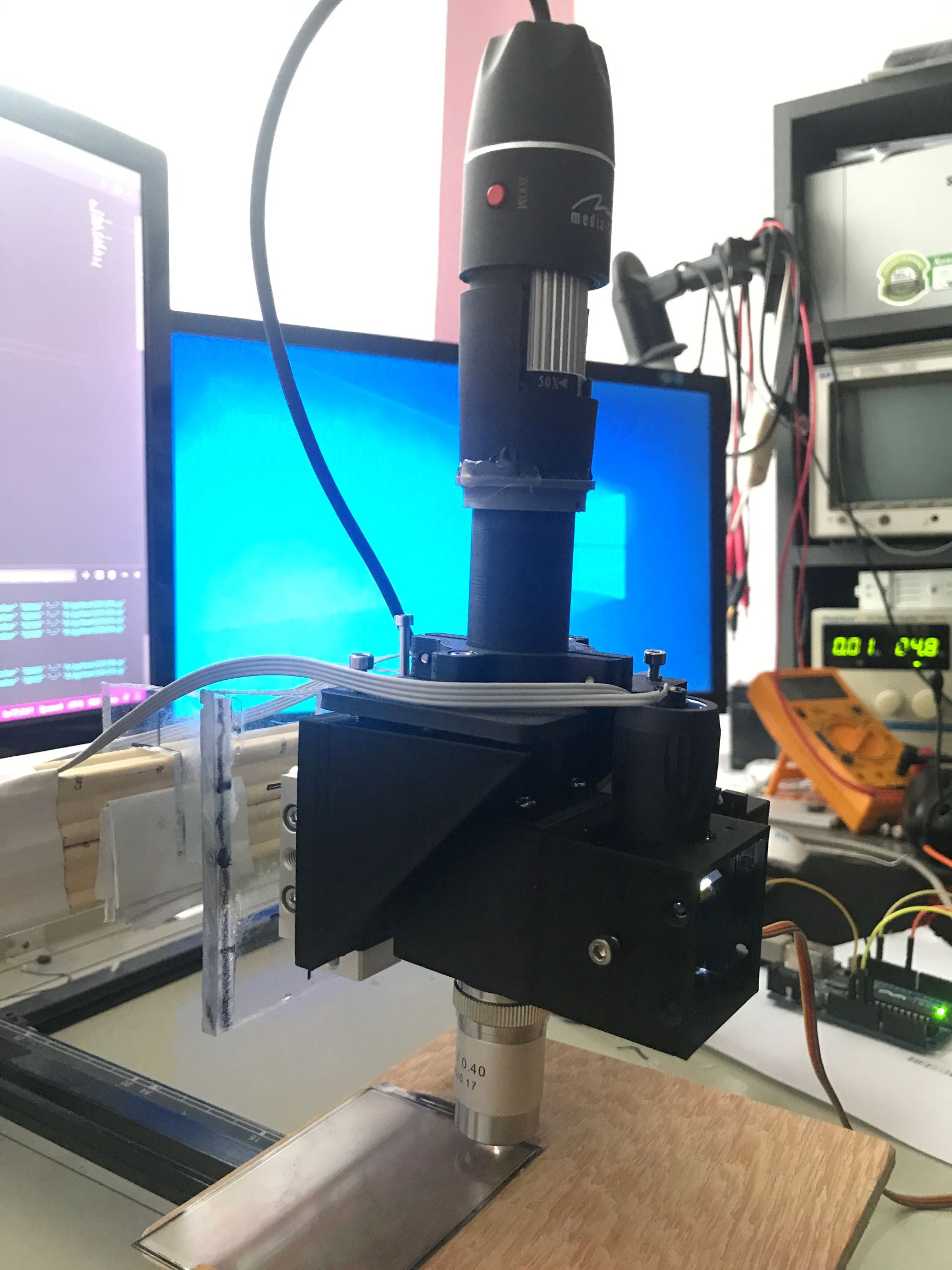
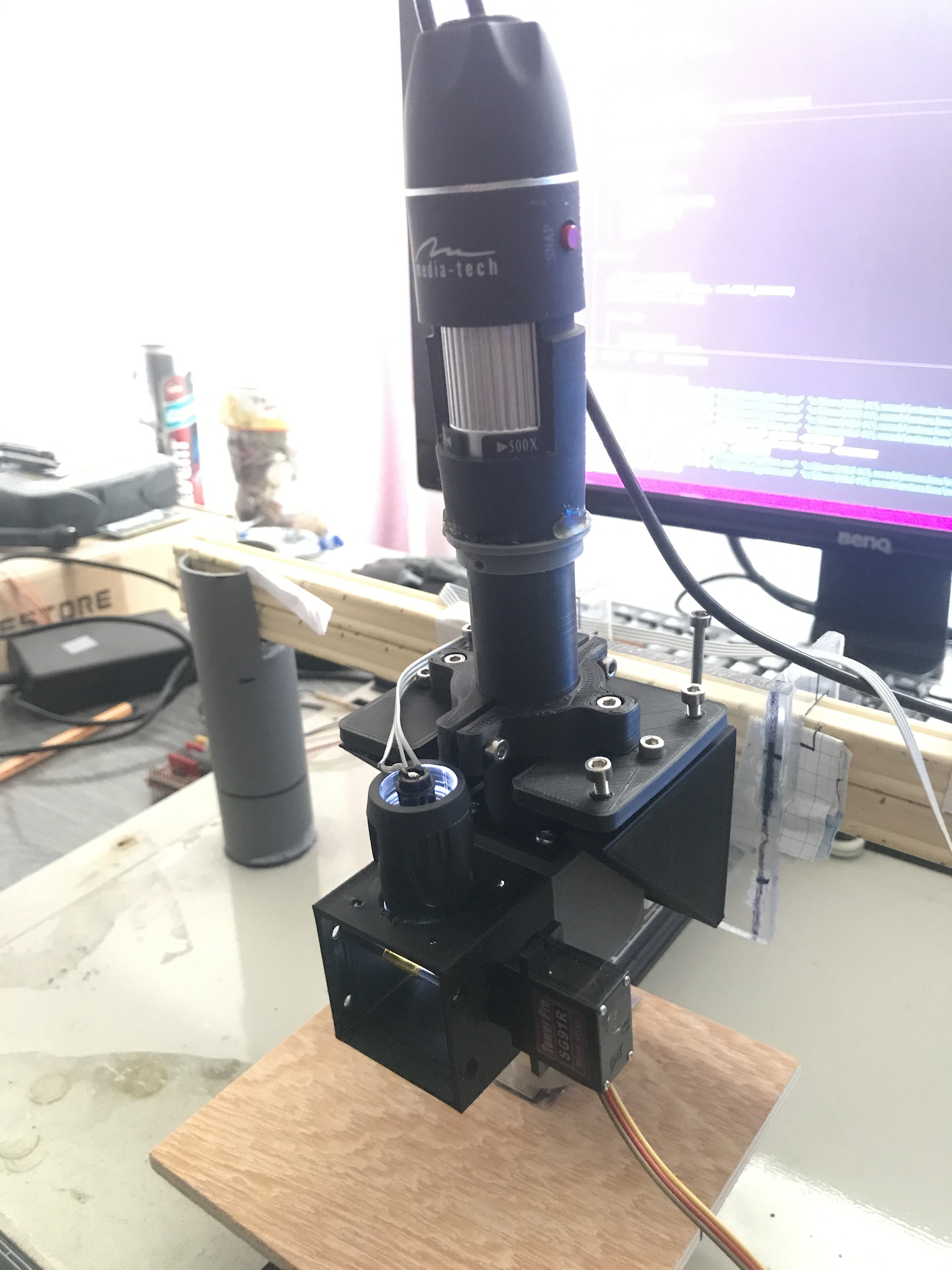
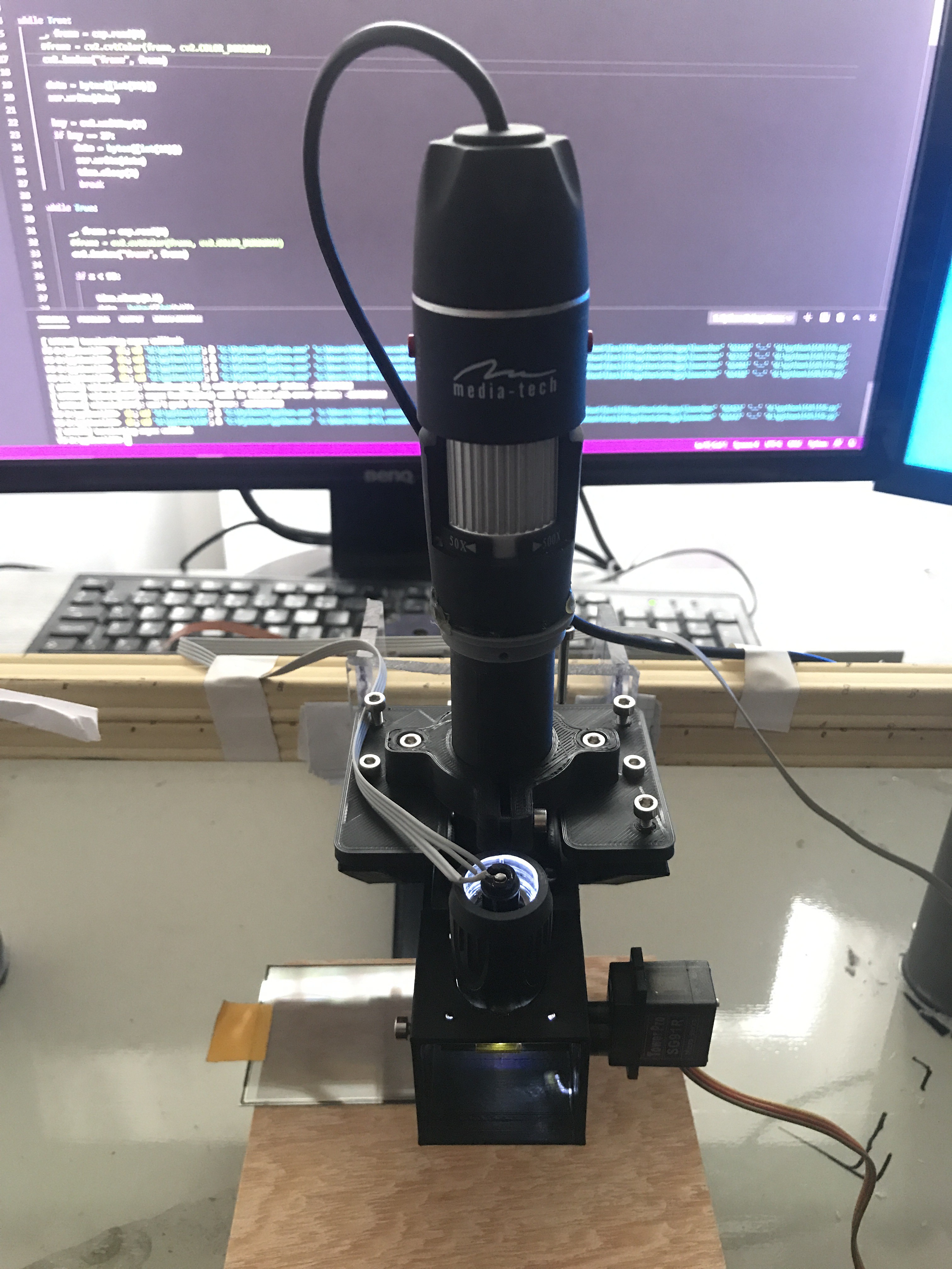
Parts description:
From top to bottop the first part is the camera, which I used a cheap USB microscope camera with a little modification. I have removed the optical lens from the camera, so the 20x objective direcly focusing the image onto the CCD surface.
The camera glued to a mounting ring, which slips onto the tube and centers it perfectly. The tube is act as a spacer. This tube mounted to the leveling plate with a two part clamp part. The clamp screws to the leveling plate. I have designed a 3 pont leveling system, which helps to set the perpendicular angle between the microscope and the sample. It is important to set it perpendicular, because we can loose light intensity.
After the tube I have designed a cube which contains the beam splitter and this part screws onto the tube above, with help of some screws.
The objective simply screws into the cube, it is not the perfect way to do it, but it works.
At this point the microscope is functional, do not need the second cube. I have tested it at this point an worked very well.
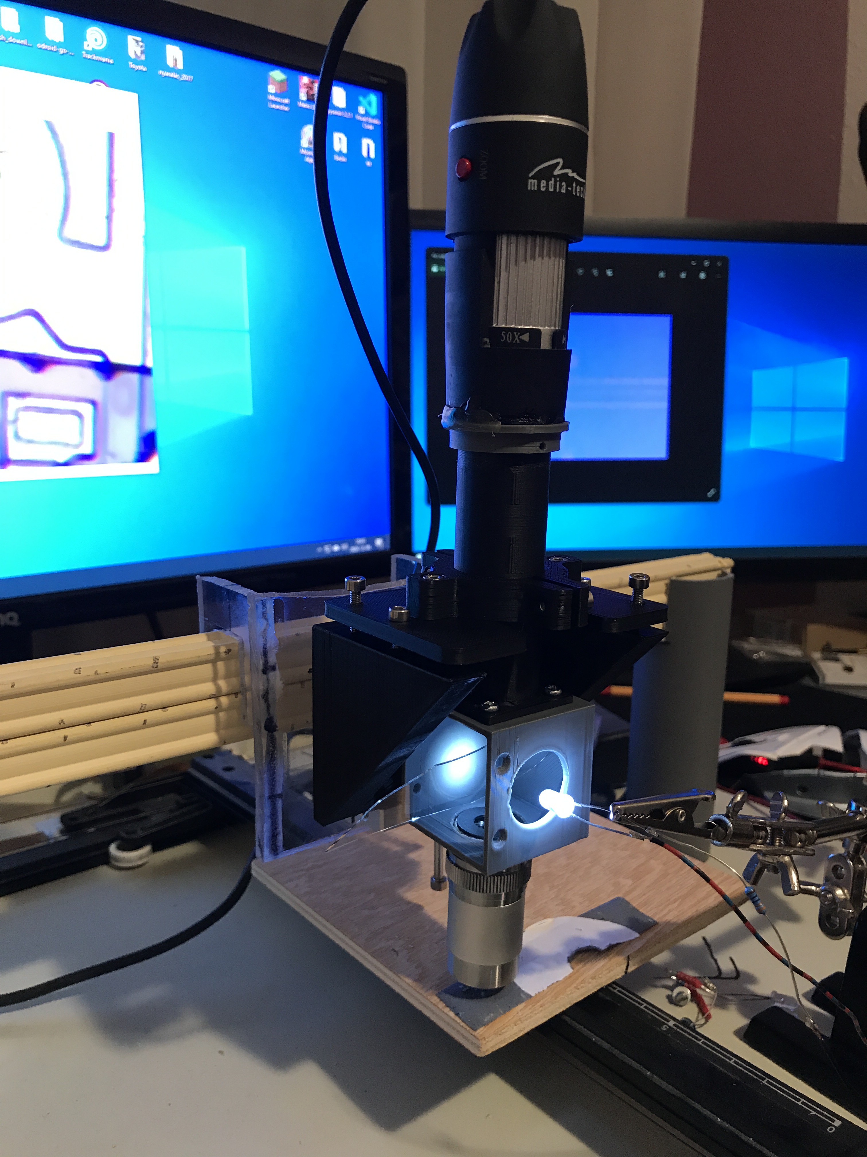
The reason I designed a second cube with a diffraction grating, because with this I can now sellect a specified light wavelength. If you shine a white light onto the surface of a grating it will gives you different color lights (wavelength).
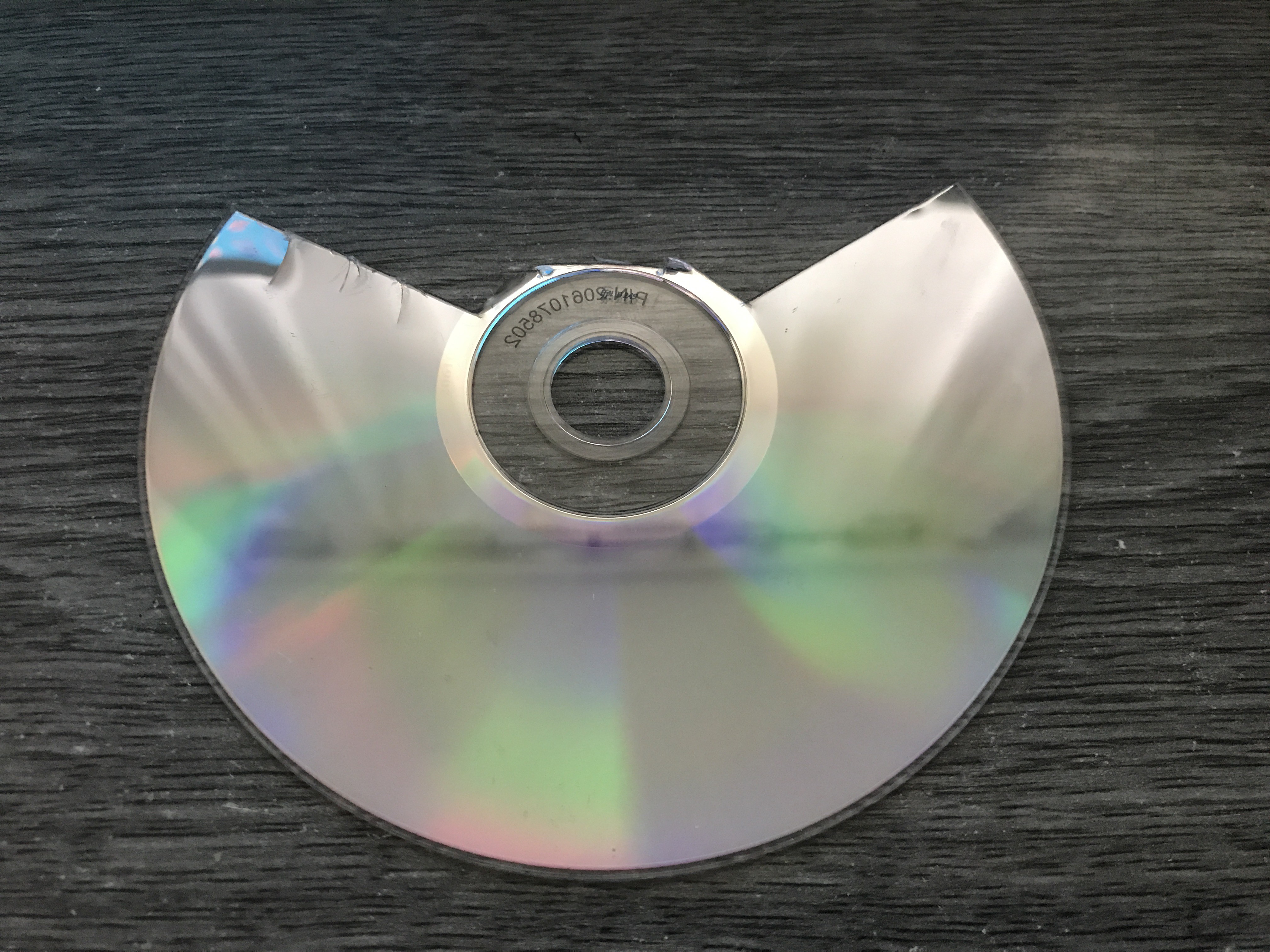
I get the grating form a old CD, but you can use DVD disk for this purpose, just keep in mind the direction you cut. The best way if you heat it up a little bit and cut it in radial dirrection.
The grating how it works:
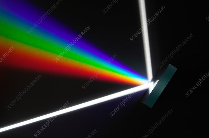
You can see it not only gives you different wavelength it act as a mirror as well. I designed a motorised rotating system for the grating, so it can be set to a certain angle, with this I can select what light wavelength I want to light the sample surface. In case I set the grating 45 degre for the incident light, it act as a mirror, so I get a white light.
Check the result:
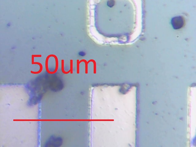
I have checked the FOV, if my calculation was correct, I was aiming for a 100x100 micrometer FOV. I had a display which on I find some ruler. These ruler on the edge of the display, where probably they calibrated there mesaurement machines:
This picture not created with the reflective microscope, just made it for navigation purposis. What you see there is lines, where every line mean 50um distance.
Here is the picture with the microscope I made:
The middle line is the 0 marking, as you can see my calculations was about right with the FOV it is 100um in X horizontal direction.
For distance scale I have used a human hair, to show the relative size. A single human hair diameter is around 50um, so lets see the pictures I took with white light:
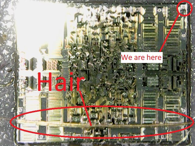
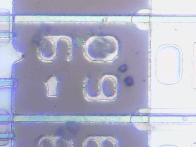
This is a IC without its package, just the bare die.


The above picture was taken from a Texas Instrument 339 operation amplifier die. It is made from 3 pictures, and it says probably the year it was designed 1996 and the company who made it TI.
Next is a AMOLED display from a Samsung Galaxy S8 phone:
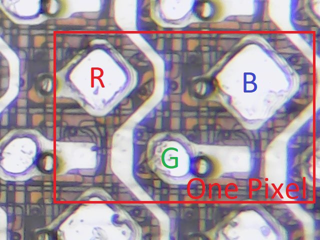
I marked the sub-pixels, the sub-pixel colors may not be in the right order, but you can see the point. Under the pixel layer is the TFT layer (Thin Film Transistor) which turns on and off the pixels.
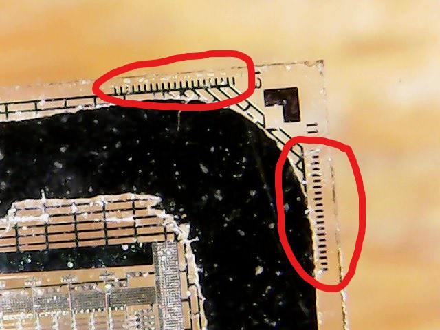
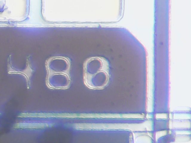
An other type of display I have is a regular LCD display, which you already see is with the ruler. This display is a 480x320 pixel screen:

As I mentioned this display has 480x320 pixel which means, the actual sub-pixel count is 960x480. The display has line count etched on to it:
Result of the selective wavelength:
I have wrote I can select the wavelength of light by rotating the grating, whith this I can measure the reflectance at every selected wavelength by the camera.
Here is the demo how it works:
For the video, I removed the side cover so we can see better what happening inside. The result image I have got is looks like this (in a gif):
Watch the transistor how it changing intensity by changing the wavelength of light.
If you read all the way down here, thank you! I hope you found it interresting.