 Manuel Tosone
Schematic
I spent the last two days working on the schematic for the first prototype, here is what I came up with.
I finally decided on what battery to use, the board will be powered by 6 AA. I have a design in mind for a case in which 6 AAs fit well.
The plan is to have the board assembled by JLCBCB and so I tried to optimize the BOM.
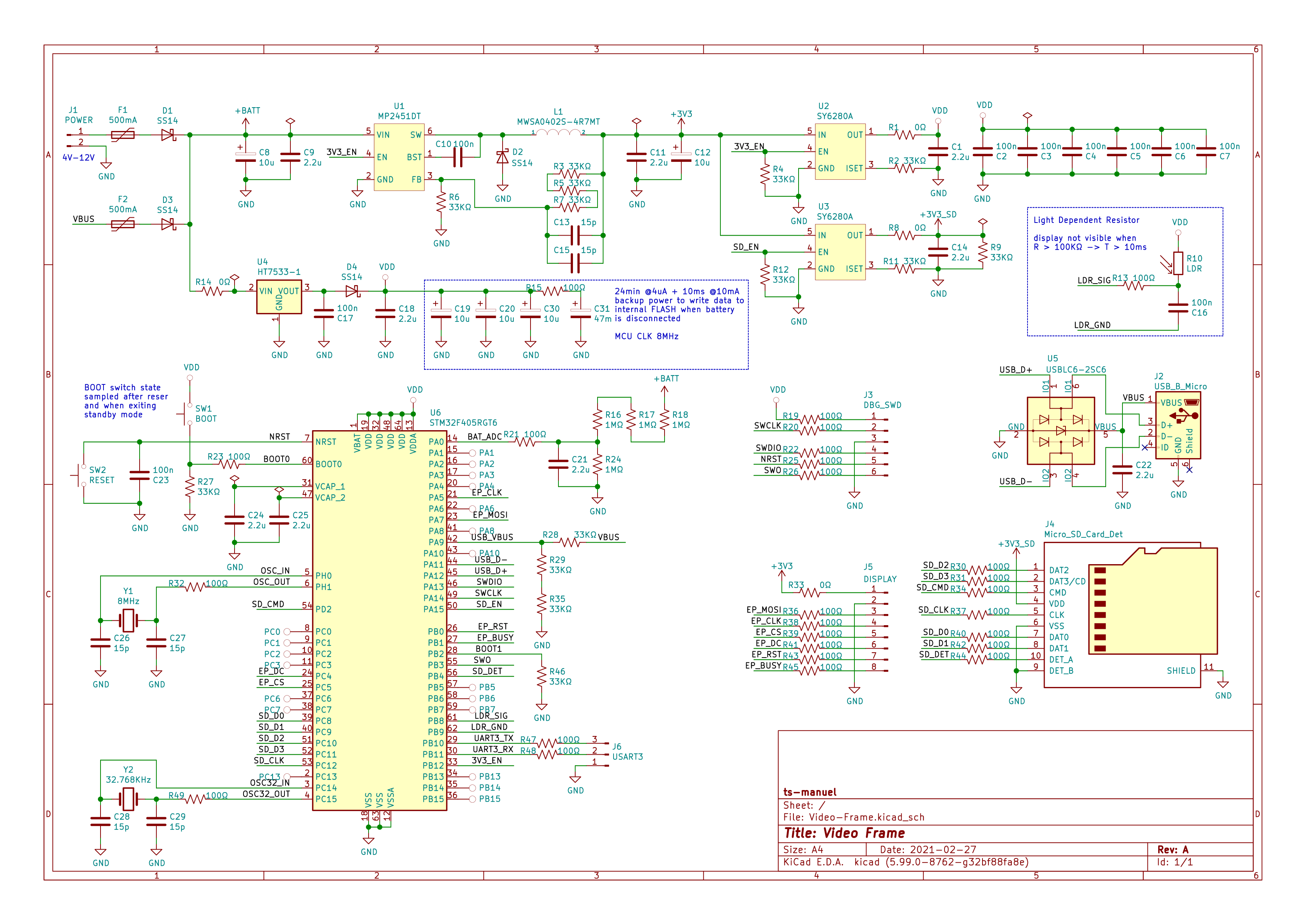
Power Section
The board can be powered either from batteries or from the USB connector. The power supply is divided into two paths, there is a switching regulator and an LDO to supply power during sleep. The reason for having two regulators is that the MP2451DT DC-DC converter has an efficiency greater than 85% with a 100mA current load but, due to the switching losses, the efficiency drops drastically at low loads. The datasheet for the microcontroller states a power consumption of 4uA in Stand-By mode. The HT7533 LDO has a quiescent current of only 2.5uA. The two SY6280A are power-distribution switches. U2 switches power to the microcontroller and is used to isolate VDD from the 3.3V when the DC-DC converter is disabled. U3 switches power to the SD-Card, it is used to disable the SD-Card while the screen is busy updating to save power.
R16, R17, R18, R24 form a potential divider that's used to measure the battery voltage. This makes it possible to detect when the batteries are running low and to display a low battery icon on the screen.
R10 is a Light Dependent Resistor, it's used to measure the ambient light. Since e-paper displays have no backlight and are not visible in the dark, there's no point in updating the display if nobody is able to see it. An LDR has a resistance that varies with the amount of light that shines on it. The resistance varies from a couple of hundred ohms, when shining a bright flashlight on it, to hundreds of kiloohms, when in complete darkness. The way the resistance is measured is by determining how long a known capacitor takes to charge from a fixed supply voltage. This mechanism is quite clever and doesn't consume any power when the resistor is not measured.
MCU Section
The microcontroller is an STM32F405RG, it has 1024KB of FLASH and 192 KB of RAM plus all the required peripherals. There are two quarts crystals, the 8MHz one is the main oscillator, the USB requires an external crystal. The 32.768KHz one drives the RTC that's used to wake the microcontroller every 24 minutes to update the display.
All unused pins are connected to test pads in case they are needed in the future.
C19, C20, C30 in conjunction with the 47mF supercapacitor C31, provide the energy required to power the microcontroller when the batteries are removed. C31 has enough stored energy to power the microcontroller for 24 minutes in standby mode when the power consumption is 4uA. The additional 30uF of capacitance on the VDD line are enough to power the microcontroller for 10ms after it exits standby mode. This is used to store the currently displayed frame in the internal FLASH so that the movie doesn't restart from the beginning every time the batteries are changed.
Programming the Microcontroller
There are three ways to program the microcontroller. The first is using the SWD debug interface, the second and third methods involve the bootloader. STM32 MCUs ship with a preprogrammed bootloader that can be used to program the device, in this case, either from the serial port or through the USB.
The MCU automatically enters into boot loader mode the first time it is powered on when the flash memory is empty. By pressing the BOOT button while performing a reset, the bootloader can be started at any time.
Power consumption estimation
The display updates every 24 minutes, that period of time is divided into 5 steps.
- DISPLAY INIT: The MCU wakes from sleep, enables the DC-DC converter, and initializes the display.
- DISPLAY CLEARING: During this phase, the display is busy clearing itself, the MCU is not needed.
- JPEG DECODE: The SD-Card is initialized, a new frame is loaded and decoded.
- DISPLAY UPDATE: During this phase, the display is busy updating itself, the MCU is not needed.
- SLEEP: Between every update, the MCU sleeps for 23.5 minutes.
The following table shows the power consumption for each component over each phase. Values are taken from the datasheet typical values. (Supply voltage is assumed to be 10V).
| DISPLAY INIT (800 ms) | DISPLAY CLEARING (13 s) | JPEG DECODE (8 s) | DISPLAY UPDATE (13 s) | SLEEP (23.5 min) | |
|---|---|---|---|---|---|
| LDO | 2.5 uA | 2.5 uA | 2.5 uA | 2.5 uA | 2.5 uA |
| BAT PDIV | 2.5 uA | 2.5 uA | 2.5 uA | 2.5 uA | 2.5 uA |
| DC-DC | 85% eff + 3 uA | 85% eff + 3 uA | 85% eff + 3 uA | 85% eff + 3 uA | 3 uA |
| MCU | 40 mA | 4 uA | 40 mA | 4 uA | 4 uA |
| Display | 0.2 mA | 24 mA | 0.2 mA | 24 mA | 0 mA |
| SD-Card | 0 mA | 0 mA | 10 mA | 0 mA | 0 mA |
| TOTAL ENERGY | 35 uWh | 337 uWh | 433 uWh | 337 uWh | 48 uWh |
Summing the energy required for each phase we obtain 1.19 mWh over a period of 24 minutes, this gives an average power consumption of 2.975 mW.
Knowing this it is possible to estimate the battery life. With 6 AA batteries, each with an average capacity of 3Wh, the total capacity is 18000 mWh.
Conclusions
252 days of battery life is not bad. Looking at the table above it can be seen that there are three phases that consume the majority of the power. The DISPLAY CLEARING and DISPLAY UPDATE phases are dictated by the display. The only optimization that can be done is in the JPEG DECODE phase, perhaps with some more code optimization or by swapping the microcontroller for a lower power one.
For now, I'm happy with 252 days.
Discussions
Become a Hackaday.io Member
Create an account to leave a comment. Already have an account? Log In.