 Evan
EvanI apologize for the long delay since the last update. I'm still here, making spurts of progress here and there.
Since the last log, I've worked on a number of things:
- Figuring out why NVMe / PCIe wasn't working
- Successfully getting the Pi to talk to the battery pack through TI's HDQ protocol.
- Unsuccessfully attempting to get the Pi to talk to the iPad's Wifi chip through SDIO.
- Redesigning the PCB to fix some earlier issues.
NVMe
On my previous revision of the PCB, I had added a M.2 slot to allow for a 2230-sized NVMe SSD -- these are getting pretty cheap these days (around $15 for 128GB), and should be faster and more durable than eMMC.
When I tested this slot by putting an SSD in it, I couldn't see anything with lspci, etc. I tried observing with my oscilloscope and didn't see anything happening, but PCIe is a little beyond the bandwidth of my scope.
Fortunately, around this time, Arya Voronova was publishing her PCIe for Hackers series on Hackaday, and a line in this article caught my attention:
As you might expect, RX on one end connects to TX on another end, and vice-versa – it’s just like UART, but spicy.
Had I gotten TX and RX wrong? Sure enough, I had. The schematic symbol I used for the M.2 slot was labeled from the perspective of the card, not the host, so I had wired the host's TX line to the card's TX line. Don't trust random symbols — check the datasheet!
I designed a little interposer board that fits in the M.2 slot, swaps TX and RX, and has another M.2 slot on top where you can put the SSD. This (and some reflow of a few bad solder joints, a perennial problem with this project) fixed the issue and got NVMe working perfectly.
The interposer board is too big to fit inside the iPad case, but it let me verify the fix before ordering and assembling a whole new board revision.
SWI? HDQ? 1-Wire?
The iPad's battery connector has a pin named BATT_SWI_CONN_R, which is used for serial communication between the processor and the battery. From what I discovered in online research, Apple devices from this era all used TI battery controller chips which speak the HDQ protocol, a proprietary single-wire interface that only seems to show up on these TI battery controllers. For reasons, Apple decided to rename this "SWI" (presumably, "single-wire interface") rather than just calling it HDQ.
I wanted to make sure I could get the Pi talking to the battery with just a trace wired between a GPIO pin and the battery's SWI pad. If I needed extra hardware to make this communication work, it would be nice to know before ordering a board revision.
First things first, I wanted to double check that the battery actually spoke HDQ, so I flashed this Arduino sketch from mozzwald onto an Arduino Uno and hooked it up. This worked perfectly:
iPhone 4G Battery Detected
Device: bq27541
Firmware: v1.25
Hardware: 0xB5
Remaining Capacity: 1166 mAH
Full Charge Capacity: 6264 mAH
Design Capacity: 6500 mAH
Time to empty: N/A, not discharging
Time to full: N/A, not charging
State of Charge: 19%
Battery Voltage: 3.73V (3730mV)
Temperature: 24.00�C / 75.38�F / 2971 raw
Charge Cycle Count: 146 times
(Looks like the battery thinks it's full-charge capacity is 96% what it was when it was new. Pretty good for a 13-year-old battery!)
Moving back to Pi land, I hooked up some jumper wires between a Pi 4 and the battery's ground / SWI contacts, and set about trying to get the Pi to speak HDQ.
In the Linux kernel, there's a driver called bq27xxx_battery_hdq, which sounds perfect -- I want to talk to a BQ27541 over HDQ. However, it turns out that this uses the Linux kernel's 1wire subsystem. HDQ and 1wire aren't actually compatible -- they're close enough at the physical layer that TI made their OMAP processors capable of speaking either, and the Linux driver for this hardware can set it into HDQ mode. This isn't helpful for me, though, since the Pi doesn't use an OMAP processor.
However, there's a w1-gpio implementation which can use an arbitrary GPIO pin to implement 1wire. (Within the linux kernel, the shorthand used for 1wire is w1, presumably because you can't start C identifiers with a number.). I set about patching this to speak HDQ well enough for the bq27xxx_battery_hdq driver. It didn't immediately work -- some transactions would work okay, but some would fail.
To help figure out what it was doing wrong (and as an interesting diversion), I ended up also writing a Saleae plugin for decoding HDQ (or, really, any serial protocol that encodes 0s and 1s as short/long pulses). This was helpful in diagnosing issues, especially when I started toggling a different GPIO pin during different sections of my patched w1-gpio code so I could follow along with the execution of my driver code.
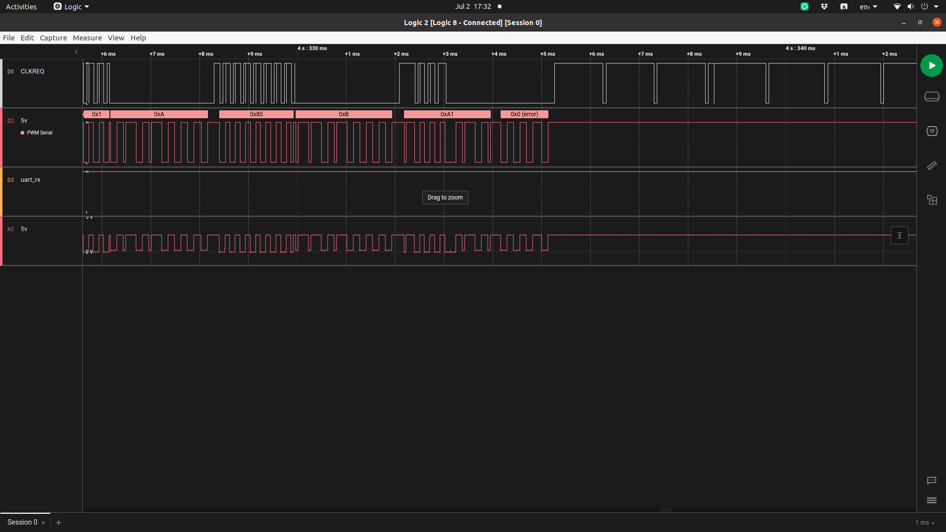
The code isn't pretty (definitely not going to get merged into the mainline kernel in this state), and it almost won't speak 1Wire anymore, but I have a driver that works!
Why won't the BCM4329 respond on SDIO?
The iPad's BCM4329 wifi/bluetooth controller is not on its logic board, it's on a skinny PCB that runs down the middle of the iPad from the logic board at the top to the 30-pin connector at the bottom. It would be convenient to be able to use this, rather than the CM4's wifi, because it's already in the right place for the iPad's antenna connectors. If I were to use a wifi CM4, I'd need to find an antenna extension cable / splitter to go from the CM4's single antenna port to the iPad's two antennas (or pick one and deal with poor reception if the iPad is facing the wrong way).
Using a breakout board I designed ages ago, I hooked up this PCB to the CM4IO with jumper wires. (I'm using the CM4 and CM4IO for this testing, rather than a Pi 4, because I think the SDIO is 1.8V, and you can change the IO voltage of the CM4 to 1.8V rather than needing a bunch of level shifters.)
As usual, I've written a device tree overlay for the BCM4329, and I can see that the CM4 is attempting to send messages on the SDIO bus, but getting no response. As this excellent SiLabs article explains,
Before using a Wi-Fi part connected to the SDIO bus of a Linux system, it is necessary that the system detects the HW on the bus.
When detection succeeds, the kernel has retrieved the VID/PID for the device.
Looking for a driver matching the VID/PID is only possible if the VID/PID has been retrieved from the device.
- As as consequence, device tree changes related to your device have no effect until SDIO detection is OK.
Once I can get the wifi controller to respond at all, we should be able to make some more progress.
I assume one of two things is wrong:
- I'm doing something silly with the enable, wake, or power pins for the BCM4329
- I've already fried the BCM4329 somehow and it'll never respond
I probably ought to put the original iPad parts back in and see if wifi still works.
Having too much fun with Kicad's "Fillet Tracks" tool
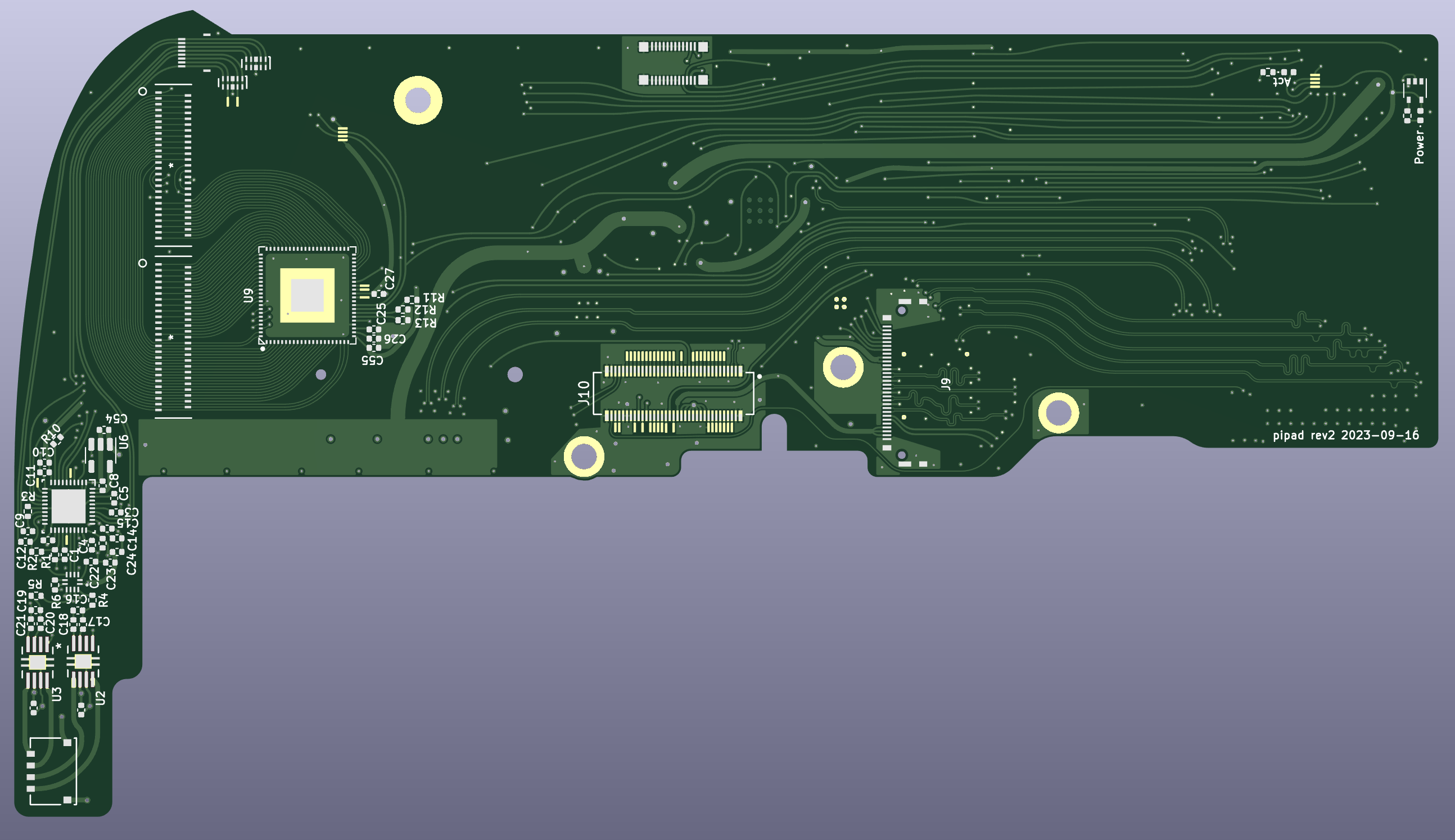
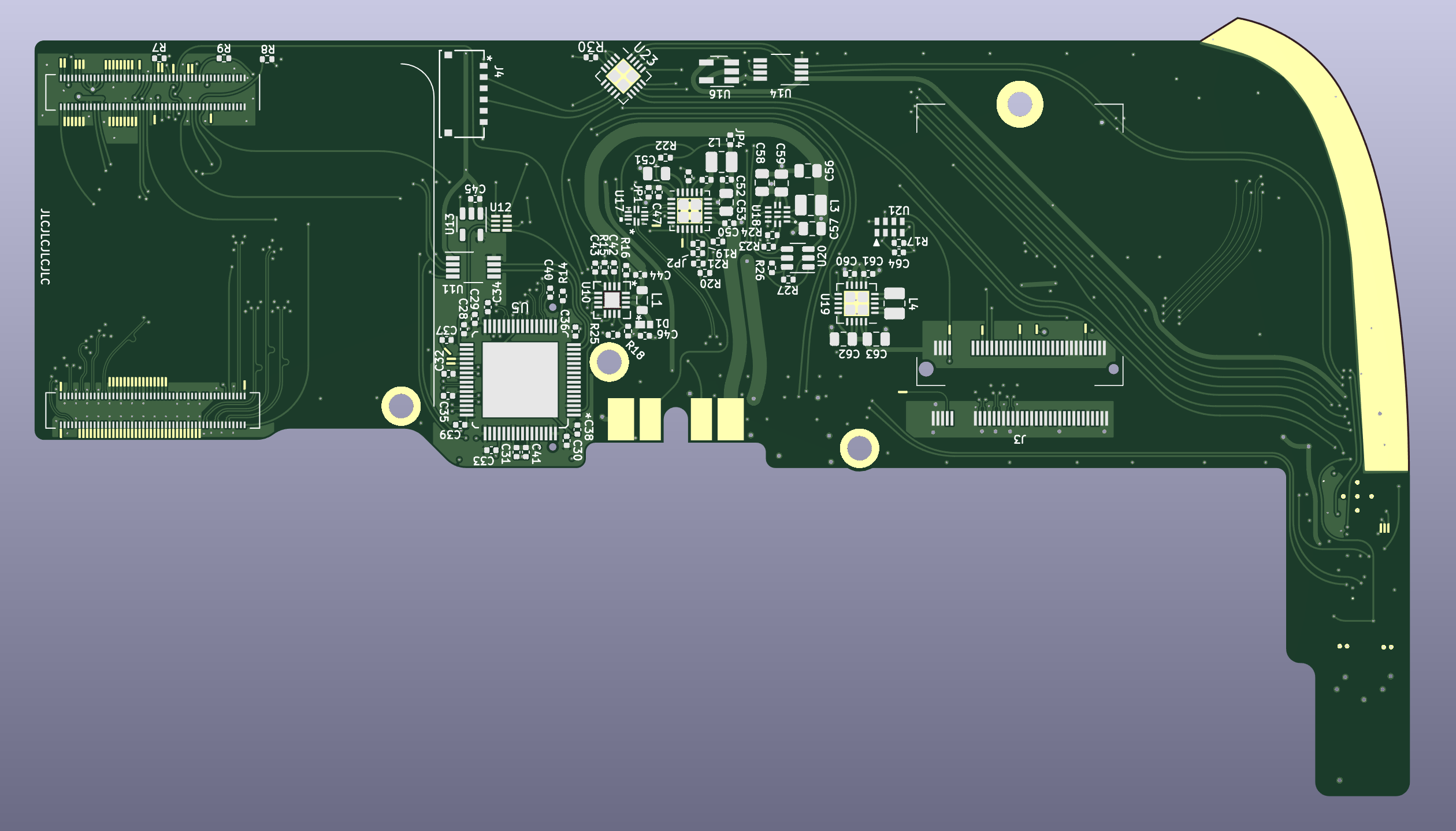
This version of the PCB fixes a few issues: the PCIe TX/RX issues mentioned above, the power switch logic, the LCD backlight driver, and certainly some other things I'm forgetting now.
I also added a trace for the HDQ pin, but didn't route traces for SDIO. I did include some tiny test pads on the board in case I want to connect SDIO later.
I've submitted my PCB order, so I expect in the next few days I'll notice some silly mistake I made in the design, or some essential part that has gone out of stock. I should probably compare my BOM and my inventory and see if I need to order anything.
Discussions
Become a Hackaday.io Member
Create an account to leave a comment. Already have an account? Log In.
The PCBs look incredible!
Are you sure? yes | no
Thanks!
Are you sure? yes | no
Glad to see, that you are still working on this project! Was worried, that you dropped it!
The fillet tracks are giving me 70s handtraced vibes.
Keep on the good work!
Are you sure? yes | no
In editing this project log, I realized that I should've made the GPIO voltage reference 1.8V instead of 3.3V on this board revision, or at least made it configurable. Currently it's hard-wired to 3.3V with a trace under one of the connectors for the CM4.
Are you sure? yes | no