 Evan
EvanI haven't worked on the audio codec part of my board in a while (I don't think I ever tested it on rev1), but it's the last major section of my rev2 PCB that needs testing. A codec is a coder/decoder -- something that encodes and decodes a digital signal --- in this case, to/from analog, so it's an ADC and DAC. In PC terminology, this would be the sound card.
The desired feature set is:
- Stereo headphone output
- Stereo speaker output
- Stereo line output (through the 30-pin connector)
- Headset microphone input (i.e. TRRS headphones that you'd use with a phone)
- The iPad's built-in microphone
- Headset detection (able to determine whether a pair of headphones is inserted into the jack, and ideally whether it includes a microphone or not)
My original design used a TLV320AIC3104 codec from TI. This has a built-in headphone amplifier, headset detection, and enough other inputs+outputs to generally fit my needs. However, this codec has one problem that made it a poor choice: it doesn't have "ground-centered" outputs.
Ground-centered outputs?
Generally speaking, most ICs can't produce voltages lower than their negative supply voltage (which is usually GND) and their positive supply voltage. A lot of audio codecs will avoid negative voltages by centering their output voltage at some voltage between the power supply and ground. However, most headphones don't really like having a DC offset in the audio signal being pumped into them. Any DC offset will simply result in a steady flow of power through your headphones' speaker coils, which gets wasted as heat. It also means you get a loud pop sound from your headphones whenever your codec turns on its outputs or when you plug in your headphones.
There are a few options to deal with this:
The easiest is to just insert DC-blocking capacitors between the output of your codec and the jack. This forms (along with whatever device you plug into the jack) an RC or RLC circuit. This creates a trade-off between capacitor size and your bass response. For typical 32-ohm headphones, in order to have the cutoff frequency be above 50Hz, you'd need approximately 100 μF of capacitance per channel. If you want to get down to 20Hz, you'd need 250 μF. That much capacitance is going to take up a nontrivial amount of space (and height) on the board. The frequency response will change depending on the impedance of whatever you plug into it, making it hard to compensate for.
The next option is called "pseudo-differential" output. In this mode, you make the ground pin of your audio connector (the sleeve in your TRS connector) not actually match your circuit board's ground, but drive it with some voltage above ground. In the simplest form, this could just be some constant DC offset, and each channel can be driven above or below that offset. If you want to increase the maximum peak-to-peak voltage range, you can pull your ground pin low when your audio signal goes high, or pull your ground pin high when your audio signal goes low, same as how an H-bridge works. (This gets a little more complicated with stereo signals.)
Pseudo-differential outputs should give you a nice flat frequency response, but sometimes they're infeasible. If you connect your audio ground (which your codec is trying to drive to, say, VCC/2) to your system ground (0V), you now have a short circuit. This isn't usually a problem with headphones, but if you were to e.g. plug your device into the aux jack of your car (which might connect the audio ground to the car's ground) while also charging your device from the car's USB port (which might connect the USB port ground to the car's ground), you'd end up with a short circuit.
The nicest option is to have your signals be ground-centered -- that is, they have an average voltage of 0, and the signal goes both positive and negative. This is more complicated because you need some way to generate a negative voltage supply, and your headphone driver needs to be able to take a non-ground-centered input and shift it down to ground for its output.
Fortunately, there are audio codecs that can provide ground-centered outputs with minimal extra circuitry required. I picked the TLV320AIC3206 from TI --- partly because it's similar to the 3104 that I had originally used, partly because TI's documentation is much more accessible to hobbyists than most other manufacturers, partly because I knew it had a Linux driver.
This chip can generate a negative voltage supply by using a charge pump architecture, only requiring two external capacitors. It can then use that negative voltage to provide ground-centered headphone outputs. (But not on its line out pins, unfortunately. Not as big of a problem, as line-level inputs are usually assumed to be high-impedance, so we can use relatively small DC-blocking capacitors.)
To enable ground-centered headphone outputs in the 3206, we just need to set one register. The Linux driver for this family of codecs was written for the 3204 (which doesn't support ground-centered output) and didn't support configuring that register, but it was an easy enough thing to patch.
I was getting really strange behavior when the ground-centered mode was enabled. Loud clicking (low-frequency square wave oscillations), no output at all, etc. Eventually I realized that I had not grounded my GND_SENSE pin. This is supposed to be grounded somewhere near the headphone jack, but I had left it floating. Once I grounded that trace, everything worked properly.
Clock sources: oh no, do I need a crystal oscillator?
I've told this story a little out of order -- Before I could worry about the ground-centered outputs, I needed to get the aic3206 to make sound at all.
All audio codecs need some sort of frequency reference, so that they output samples at a steady rate. The TLV320AIC3206 is very flexible about how you can provide that: The datasheet says:
The required internal clock of the TLV320AIC3206 can be derived from multiple sources, including the MCLK pin,
the BCLK pin, the GPIO pin or the output of the internal PLL, where the input to the PLL again can be derived
from the MCLK pin, the BCLK or GPIO pins. Although using the PLL ensures the availability of a suitable clock
signal, PLL use is not recommended for the lowest power settings. The PLL is highly programmable and can
accept available input clocks in the range of 512 kHz to 50 MHz.
I designed my board assuming that I'd just use BCLK, which is the bit clock of the I2S bus that is transferring the digital audio data between the codec and the CPU. Whenever there's audio output or input, the Raspberry Pi should be driving this clock line anyway (it's necessary for the data transfer). I left the MCLK pin floating (with a test point).
However, when initially trying to bring up the codec, I discovered that the driver requires you to pass a clock designator as the "mclk" input, and actually exits with an error if you don't specify an "mclk" clock. I could see that there was code in the driver that theoretically could set the correct registers in the codec to use BCLK as the input to the PLL, but I couldn't see anywhere that it was being called. Without the clocks properly configured, the codec won't be able to generate any audio. I reached out to the author of the clock-handling code in the aic32x4 driver to ask for guidance.
Meanwhile, I took a Si5351 clock generator board that I had lying around (a random AliExpress purchase a while ago), bodged it into the board such that its output was connected to the codec's MCLK pin, and figured out how to get it set up in my device tree such that the aic32x4 driver understood that the Si5351 was connected to MCLK. Once I had this in place, the codec worked perfectly.
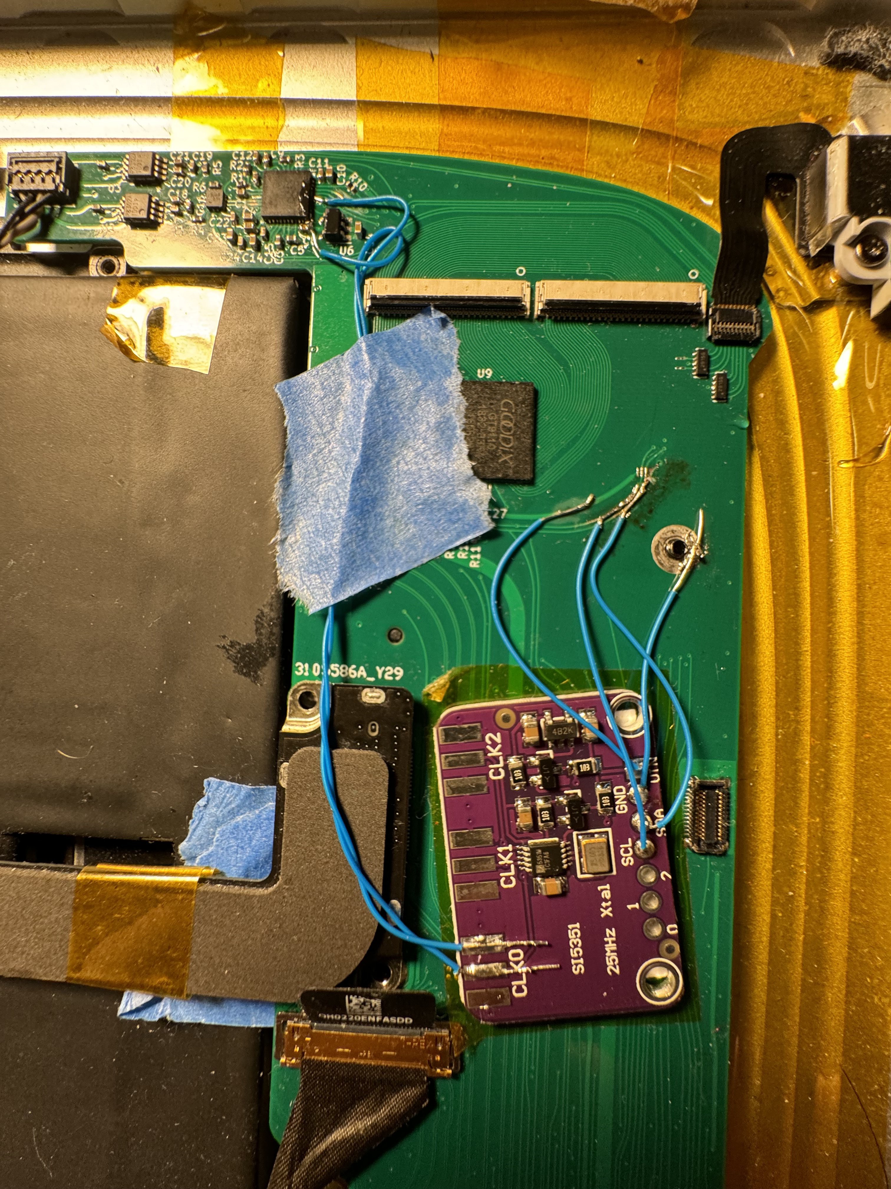
At some point, I figured out that I could short MCLK and BCLK, which would allow the codec to work the way the Linux driver configures it without the Si5351 or any other external clock.
With the help of the driver developer that I had contacted, I figured out enough about how clocks are supposed to work in the kernel to write a patch that allows me to configure the PLL to use BCLK as input, by setting this in my device tree overlay:
            tlv320aic3206: tlv320aic3206@18 {
...
                clocks = <&clocks BCM2835_CLOCK_PCM>;
                clock-names = "bclk";
...
            };
Fantastic, now I don't need any bodges for the clocks to work (just the one so that ground-centered mode works).
Headset detection
You know how your computer and phone (back when they had 3.5mm jacks, at least) will mute their speakers whenever you plug in headphones? I'd really like that same functionality on my board. In order to make this work, I need to detect whether headphones are plugged into the jack, a process creatively named "headset detection".
Some 3.5mm jacks provide a pin that acts as a switch to let you know that something is inserted, but this gives you just one bit of information. In my case, I need at least two, maybe 3 bits:
- Are there headphones plugged in?
- Do the headphones have a microphone?
- (Optionally) Are the headphones stereo?
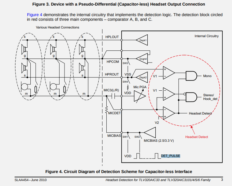
The aic3206 can answer the first two questions without any special switches in the headphone jack, just the 4 TRRS connections. This would be convenient.
Like the ground-centered mode, though, the existing Linux driver doesn't have the ability to configure the register in the aic3206 that controls headset detection. This was an easy enough patch.
Once I enabled this, however, I had an annoying ~2kHz tone in my headphones; it was a lot worse when the plug was only partly plugged in. Some headphones were worse than others, but it was audible in all of the headphones I tested.
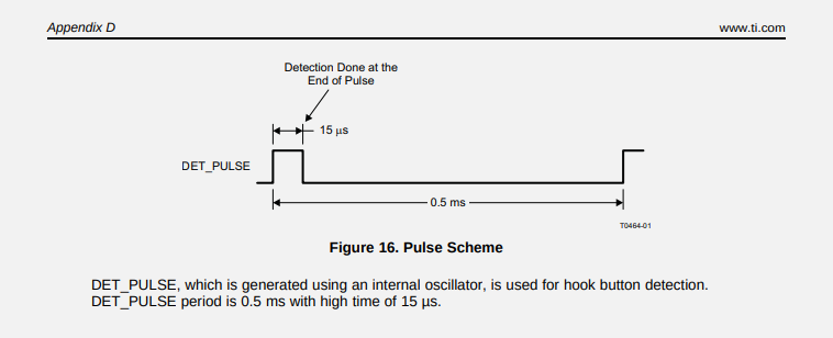
I noticed that the MICBIAS pin from the codec had a ~15 microsecond pulse every ~500 microseconds; there's a resistor connected between this pin and the sleeve of my headphone jack, meant to bias the microphone in the headphones. Theoretically, I shouldn't be able to hear this --- it should go through the microphone and back to ground --- but I think there's enough cross-talk between traces (or wires in my headphone cable) that it's audible.
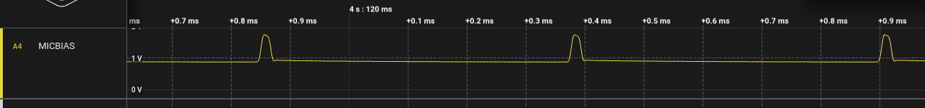
On the TI forums, I learned that the aic3206 headset detection works similarly to the aic3104 headset detection. The latter has an application note describing its functionality. From the app note, we can see that this pulse train is expected when headset detection is enabled:
Lovely. I've asked for tips on the TI forum about avoiding this audible squeal, but since I don't see any configuration registers that would change this behavior, I'm not sure there's much to do other than avoid having headset detection enabled in the chip for very long.
The 3.5mm jack in the iPad does have a "DETECT" pin, which I had only pulled out to a test pad, as I assumed that I could rely on the codec's built-in headset detection. This pin seems to be connected to the left audio channel when nothing is inserted, and, as far as I can tell, goes open when something is inserted. Perhaps I can connect this to a GPIO pin with a pull-up resistor, and when this goes high (indicating something has been plugged in) briefly enable the codec's headset detection to determine whether the headphones have a microphone or not.
Discussions
Become a Hackaday.io Member
Create an account to leave a comment. Already have an account? Log In.
As always a very interesting read. Keep up the good work. And nice, that we are getting so frequent updates.
Are you sure? yes | no
I think it's impressive that you can just casually go and patch drivers when something isn't working / supported.
Are you sure? yes | no
I'm mostly just copy/pasting existing code and modifying it to suit my needs. I might try to submit these patches upstream, then I'll really have street cred :)
Are you sure? yes | no
I was remembering this comment while submitting my first ever PR patch today.
Are you sure? yes | no
Oh nice, what's the patch?
Are you sure? yes | no
It was for MarlinFirmware: https://hackaday.io/project/190831/log/227783
Are you sure? yes | no