 Evan
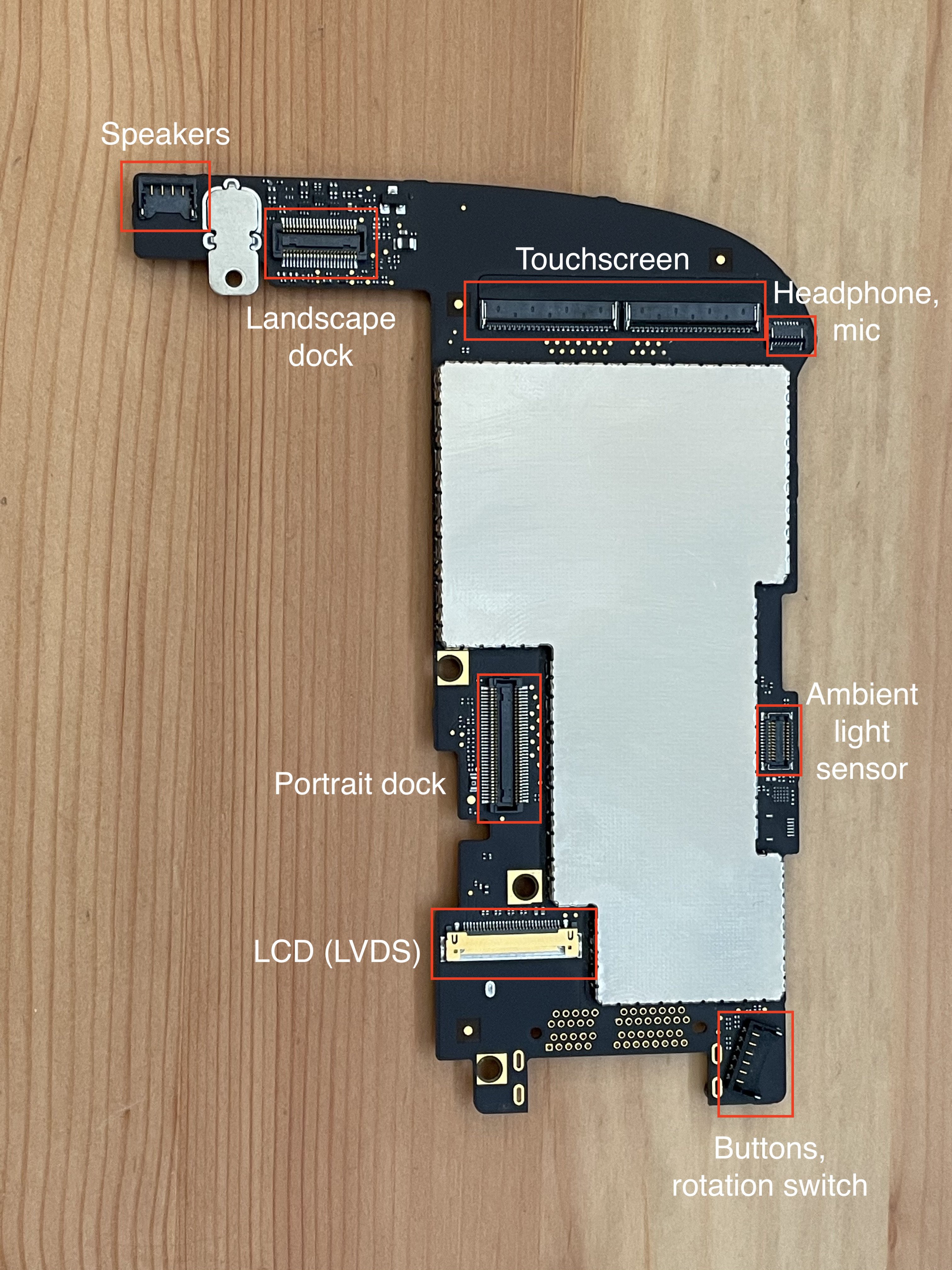
EvanI've long been ignoring the ambient light sensor flex cable that's part of the iPad's display assembly. This connects to a 24-pin board-to-board connector on the logic board, pictured on the right edge here:
Only 7 of the 24 pins are used:
- 3.0V
- SCL and SDA for i2c
- ALS_INT_L
- COMP_RST_L
- COMP_INT_L
The other 17 pins are ground.
(Fun fact: this connector, the AA03-S024VA1, is also what they used for the camera in the iPhone 3G, though with a different pin configuration. Maybe they had a lot of extras and decided to reuse it on the iPad. It's not like they were low on space in the iPad, so using a larger-than-necessary connector wouldn't be a big deal.)
The last two pins are connected in the iPad schematics to "COMPASS_RST_L" and "COMPASS_INT_L",
I've been including this connector in all my prototype PCBs, and I also created a breakout board for it. This weekend, I wired up the breakout board to a Pi 4 (just power and I2C, none of the interrupt/reset pins) and got to work trying to figure out what ambient light sensor IC is used.
What's i2c address 0x39?
By wiring up the breakout board and connecting it to a Raspberry Pi, we can see that this cable only seems to have one device on it, at address 0x39:
meatmanek@pi4:~ $ i2cdetect -y 1
     0  1  2  3  4  5  6  7  8  9  a  b  c  d  e  f
00:                         -- -- -- -- -- -- -- --
10: -- -- -- -- -- -- -- -- -- -- -- -- -- -- -- --
20: -- -- -- -- -- -- -- -- -- -- -- -- -- -- -- --
30: -- -- -- -- -- -- -- -- -- 39 -- -- -- -- -- --
40: -- -- -- -- -- -- -- -- -- -- -- -- -- -- -- --
50: -- -- -- -- -- -- -- -- -- -- -- -- -- -- -- --
60: -- -- -- -- -- -- -- -- -- -- -- -- -- -- -- --
70: -- -- -- -- -- -- -- --
That's odd. I was expecting two devices: one for the compass, one for the ambient light sensor. Maybe it's a single IC?
Searching the internet for "i2c address 0x39" brought me to https://i2cdevices.org/addresses/0x39 which gives us a few options:
- APDS-9960 - IR/Color/Proximity Sensor
- PCF8574AP - I²C-bus to parallel port expander
- SAA1064 - 4-digit LED driver
- TSL2561 - light sensor
- VEML6070 - UVA Light Sensor with I2C Interface
Hmm. 3 of those could be ambient light sensors (APDS-9960, TSL2561, VEML6070), but also surely there are more devices out there that use this address.
Not wanting to tear apart my iPad more than necessary, I took another look at iFixit's images of this flex cable:

Enhance:
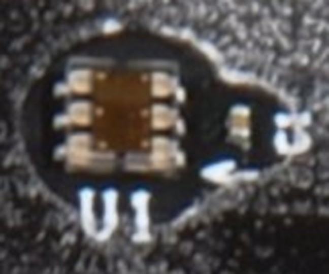

Enhance:
Looks like there's just one IC and a decoupling capacitor.
Here's what we know about this IC:
- It's the ambient light sensor.
- It's a 6-pin DFN footprint, but the size is hard to determine.
- The top of the chip is clear, exposing the die. (Makes sense for a light sensor.)
- We can see the 6 bonding wire pads.
- It uses I2C.
- It supports a power supply voltage of 3.0V
(I guess the compass may have been removed before the iPad shipped?)
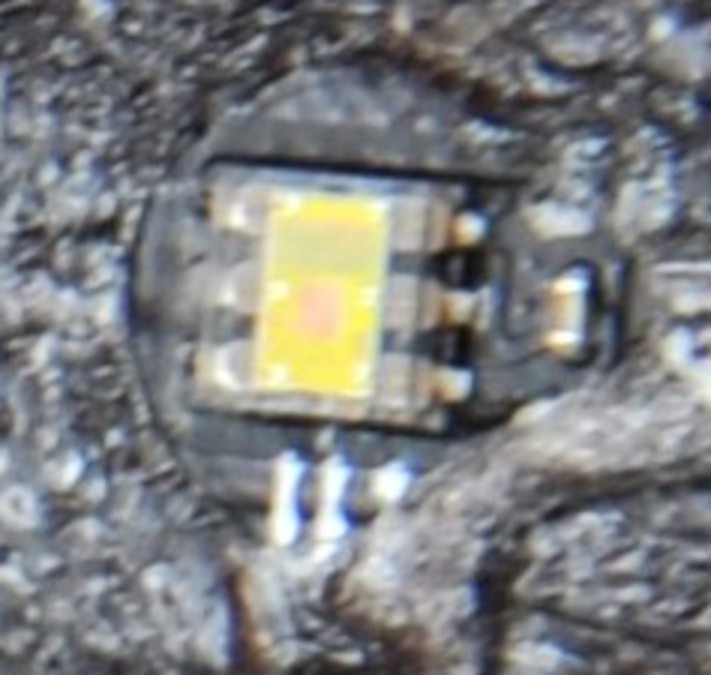
Looking at the three options from i2cdevices.org:
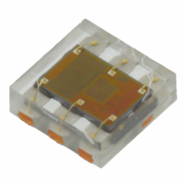
The APDS-9960 does RGB and gesture detection, and doesn't look right:

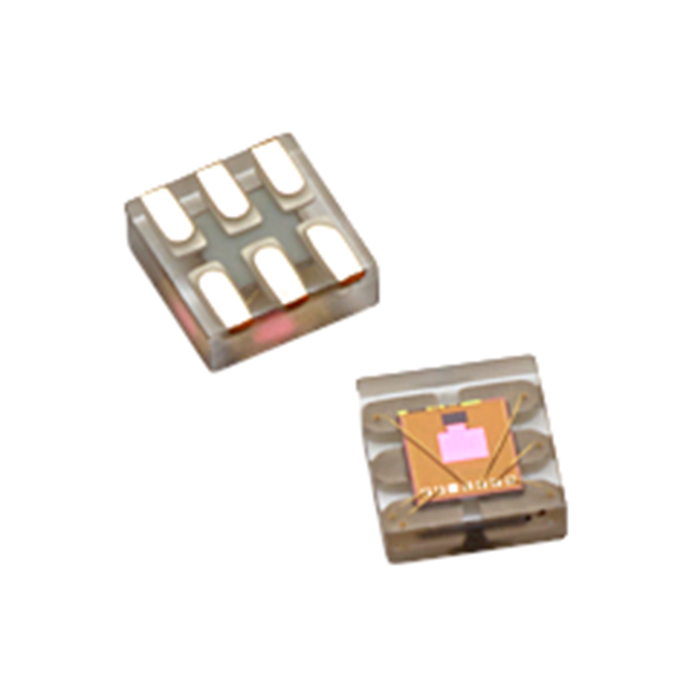
The VEML-6070 is a UV sensor, which doesn't make sense, and also it doesn't look right:

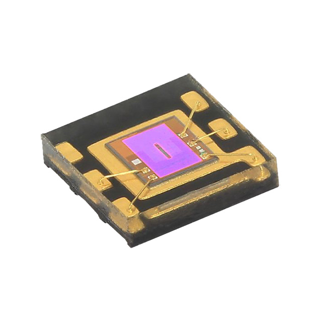
The TSL2561 looks promising:

To check if this is correct, I got the Adafruit python driver for this chip:
meatmanek@pi4:~ $ python3 -m venv venv
meatmanek@pi4:~ $ . venv/bin/activate
(venv) meatmanek@pi4:~ $  pip3 install adafruit-circuitpython-tsl2561
...
Successfully installed Adafruit-Blinka-8.34.0 Adafruit-Circuitpython-ConnectionManager-1.0.1 Adafruit-PlatformDetect-3.62.0 Adafruit-PureIO-1.1.11 RPi.GPIO-0.7.1 adafruit-circuitpython-busdevice-5.2.6 adafruit-circuitpython-requests-3.0.1 adafruit-circuitpython-tsl2561-3.3.18 adafruit-circuitpython-typing-1.10.2 pyftdi-0.55.0 pyserial-3.5 pyusb-1.2.1 rpi-ws281x-5.0.0 sysv-ipc-1.1.0 typing-extensions-4.10.0
(venv) meatmanek@pi4:~ $ cat > tsl2561.py
# This is from https://learn.adafruit.com/tsl2561/python-circuitpython
import board
import busio
import adafruit_tsl2561
i2c = busio.I2C(board.SCL, board.SDA)
sensor = adafruit_tsl2561.TSL2561(i2c)

print('Lux: {}'.format(sensor.lux))
print('Broadband: {}'.format(sensor.broadband))
print('Infrared: {}'.format(sensor.infrared))
print('Luminosity: {}'.format(sensor.luminosity))
(venv) meatmanek@pi4:~ $ python ./tsl2561.py
Traceback (most recent call last):
  File "/home/meatmanek/./tsl2561.py", line 5, in <module>
    sensor = adafruit_tsl2561.TSL2561(i2c)
             ^^^^^^^^^^^^^^^^^^^^^^^^^^^^^
  File "/home/meatmanek/venv/lib/python3.11/site-packages/adafruit_tsl2561.py", line 75, in __init__
    raise RuntimeError(
RuntimeError: Failed to find TSL2561! Part 0x0 Rev 0x0
From reading the code, it seems to look at register 0x0A and report the upper 4 bits as the part number and the lower 4 bits as the revision number. The TSL2561 should have the part number set to 0x5.
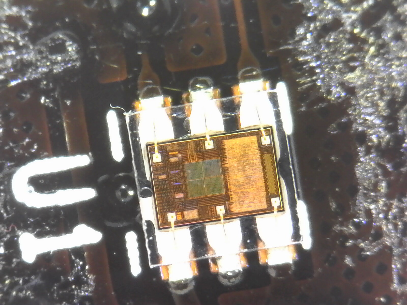
Maybe it's some other chip. Let's see how many other 6-pin I2C light sensors that support 3.0V power exist on Digikey. 124? We're going to need more information. I decided to pull the flex PCB off my display to get a higher-resolution photo of the IC itself.
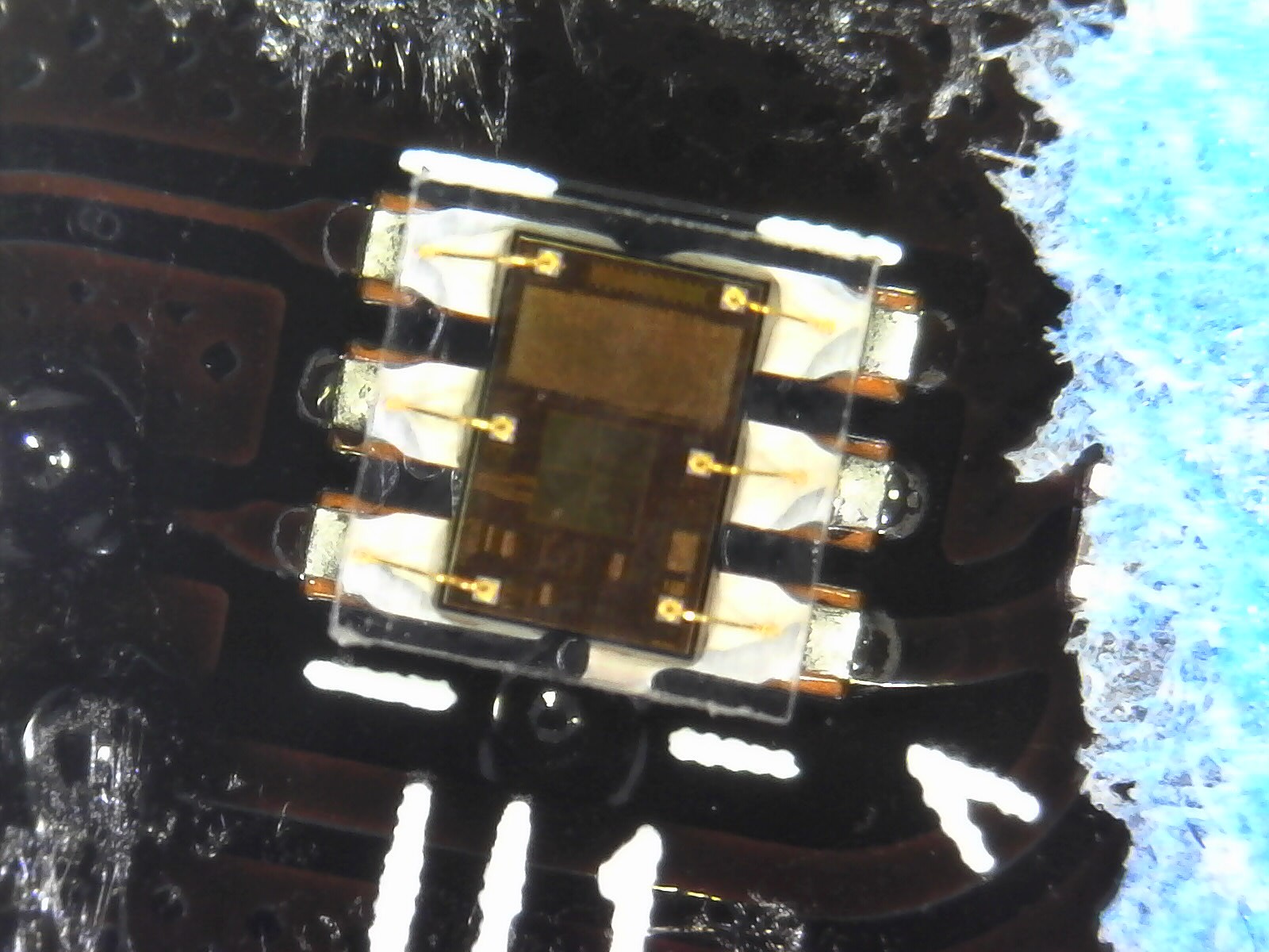
This is actually surprisingly helpful. We can see the bond wires and the patterns on the IC, which we can try to match against the Digi-Key photos.
The TSL2561 looks promising, but we know that the Adafruit library for it doesn't work:
Other manufacturers look different:
Based on this, I'm assuming it's another chip from ams-OSRAM, in the same family as the TSL2561.
Adafruit also has a driver for the TSL2591, since they sell that breakout board too. Let's try that?
meatmanek@pi4:~ $ cat > tsl2591.py
# adapted from https://learn.adafruit.com/adafruit-tsl2591/python-circuitpython
import board
import adafruit_tsl2591
i2c = board.I2C()
sensor = adafruit_tsl2591.TSL2591(i2c, address=0x39)

print('Light: {0}lux'.format(sensor.lux))
print('Visible: {0}'.format(sensor.visible))
print('Infrared: {0}'.format(sensor.infrared))

meatmanek@pi4:~ $ . venv/bin/activate
(venv) meatmanek@pi4:~ $ python ./tsl2591.py
Traceback (most recent call last):
  File "/home/meatmanek/./tsl2591.py", line 2, in
    import adafruit_tsl2591
ModuleNotFoundError: No module named 'adafruit_tsl2591'

(venv) meatmanek@pi4:~ $ pip3 install adafruit-circuitpython-tsl2591
Looking in indexes: https://pypi.org/simple, https://www.piwheels.org/simple
...
Successfully installed adafruit-circuitpython-tsl2591-1.3.12
(venv) meatmanek@pi4:~ $ python ./tsl2591.py
Traceback (most recent call last):
  File "/home/meatmanek/./tsl2591.py", line 4, in
    sensor = adafruit_tsl2591.TSL2591(i2c, address=0x39)
             ^^^^^^^^^^^^^^^^^^^^^^^^^^^^^^^^^^^^^^^^^^^
  File "/home/meatmanek/venv/lib/python3.11/site-packages/adafruit_tsl2591.py", line 132, in __init__
    raise RuntimeError("Failed to find TSL2591, check wiring!")
RuntimeError: Failed to find TSL2591, check wiring!
Looking at line 132 in adafruit_tsl2591.py, it looks like it's also checking a register to see if the chip has the right device ID:
    def __init__(self, i2c: I2C, address: int = _TSL2591_ADDR) -> None:
        ...
        # Verify the chip ID.
        if self._read_u8(_TSL2591_REGISTER_DEVICE_ID) != 0x50:
            raise RuntimeError("Failed to find TSL2591, check wiring!")
        ...
At this point I start looking through the Linux drivers for TSL* light sensor ICs:
meatmanek@brix1:~/raspberrypi-linux$ (ccache arm64) git grep -i ,tsl Documentation/
Documentation/devicetree/bindings/iio/light/amstaos,tsl2563.yaml:$id: http://devicetree.org/schemas/iio/light/amstaos,tsl2563.yaml#
Documentation/devicetree/bindings/iio/light/amstaos,tsl2563.yaml:      - amstaos,tsl2560
Documentation/devicetree/bindings/iio/light/amstaos,tsl2563.yaml:      - amstaos,tsl2561
Documentation/devicetree/bindings/iio/light/amstaos,tsl2563.yaml:      - amstaos,tsl2562
Documentation/devicetree/bindings/iio/light/amstaos,tsl2563.yaml:      - amstaos,tsl2563
Documentation/devicetree/bindings/iio/light/amstaos,tsl2563.yaml:        compatible = "amstaos,tsl2563";
Documentation/devicetree/bindings/iio/light/amstaos,tsl2591.yaml:$id: http://devicetree.org/schemas/iio/light/amstaos,tsl2591.yaml#
Documentation/devicetree/bindings/iio/light/amstaos,tsl2591.yaml:    const: amstaos,tsl2591
Documentation/devicetree/bindings/iio/light/amstaos,tsl2591.yaml:            compatible = "amstaos,tsl2591";
Documentation/devicetree/bindings/iio/light/tsl2583.yaml:      - amstaos,tsl2580
Documentation/devicetree/bindings/iio/light/tsl2583.yaml:      - amstaos,tsl2581
Documentation/devicetree/bindings/iio/light/tsl2583.yaml:      - amstaos,tsl2583
Documentation/devicetree/bindings/iio/light/tsl2583.yaml:                compatible = "amstaos,tsl2581";
Documentation/devicetree/bindings/iio/light/tsl2772.yaml:      - amstaos,tsl2571
Documentation/devicetree/bindings/iio/light/tsl2772.yaml:      - amstaos,tsl2671
Documentation/devicetree/bindings/iio/light/tsl2772.yaml:      - amstaos,tsl2771
Documentation/devicetree/bindings/iio/light/tsl2772.yaml:      - amstaos,tsl2572
Documentation/devicetree/bindings/iio/light/tsl2772.yaml:      - amstaos,tsl2672
Documentation/devicetree/bindings/iio/light/tsl2772.yaml:      - amstaos,tsl2772
Documentation/devicetree/bindings/iio/light/tsl2772.yaml:                compatible = "amstaos,tsl2772";
Documentation/devicetree/bindings/spi/cdns,qspi-nor.yaml:      cdns,tslch-ns:
Documentation/devicetree/bindings/trivial-devices.yaml:          - taos,tsl2550
Looks like there are 4 distinct drivers, some handling multiple chips. We've already eliminated the tsl2561 (handled by the tsl2563 driver) and the tsl2591 (handled by its own driver), let's try the tsl2571 (handled by the tsl2772 driver). I create this device tree overlay file:
#include <dt-bindings/interrupt-controller/irq.h>

/dts-v1/;
/plugin/;

/ {
    compatible = "brcm,bcm2835";

    fragment@0 {
        target = <&i2c1>;
        __overlay__ {
            #address-cells = <1>;
            #size-cells = <0>;
            status = "okay";

            als@39 {
                    compatible = "amstaos,tsl2571";
                    reg = <0x39>;
            };
        };
    };
};
This should get the tsl2772 driver loaded and configured to talk to a tsl2571 on i2c bus 1, address 0x39.
When loading this dtoverlay file, I get an error:
meatmanek@pi4:~ $ sudo dtoverlay pipad-als
meatmanek@pi4:~ $ dmesg | grep tsl
[   61.915038] tsl2772 1-0039: supply vdd not found, using dummy regulator
[   61.916654] tsl2772 1-0039: supply vddio not found, using dummy regulator
[   61.943592] tsl2772 1-0039: tsl2772_probe: i2c device found does not match expected id
[   61.943846] tsl2772: probe of 1-0039 failed with error -22
Looks like more of the same problems. I patched the code to print out the ID it found (0x93). Looking at the code in this driver that checks the chip ID, none of the chips supported by this driver would have ID 0x93 -- it only supports 0x0*, 0x2*, and 0x3*:
/* Use the default register values to identify the Taos device */
static int tsl2772_device_id_verif(int id, int target)
{
    switch (target) {
    case tsl2571:
    case tsl2671:
    case tsl2771:
        return (id & 0xf0) == TRITON_ID;
    case tmd2671:
    case tmd2771:
        return (id & 0xf0) == HALIBUT_ID;
    case tsl2572:
    case tsl2672:
    case tmd2672:
    case tsl2772:
    case tmd2772:
    case apds9930:
        return (id & 0xf0) == SWORDFISH_ID;
    }

    return -EINVAL;
}
Around this time I decided to see if I could get a better photo of the IC:
Quite a bit clearer.
Back to the search -- if we've tried the 2561, 2571, and 2591, maybe it's the 2581? I google for tsl2581 and this image pops up:

That looks extremely close (closer than the 2561/2571 image does), let's give it a try. Just a 1-character change to my device tree overlay file, and:
meatmanek@pi4:~ $ sudo dtoverlay pipad-als
meatmanek@pi4:~ $ dmesg | grep tsl
[  181.899420] tsl2583 1-0039: Light sensor found.
Well, that's encouraging!
Since this is an iio driver, the sysfs files live in a directory under /sys/bus/iio/devices:
meatmanek@pi4:~ $ cd /sys/bus/iio/devices/iio\:device0/
meatmanek@pi4:/sys/bus/iio/devices/iio:device0 $ ls
in_illuminance_both_raw   in_illuminance_calibscale            in_illuminance_input_target                in_illuminance_ir_raw     of_node    uevent
in_illuminance_calibbias  in_illuminance_calibscale_available  in_illuminance_integration_time            in_illuminance_lux_table  power
in_illuminance_calibrate  in_illuminance_input                 in_illuminance_integration_time_available  name                      subsystem
meatmanek@pi4:/sys/bus/iio/devices/iio:device0 $ cat in_illuminance_ir_raw
0
meatmanek@pi4:/sys/bus/iio/devices/iio:device0 $ cat in_illuminance_both_raw
0
Turns out that once you read in_illuminance_input, then in_illuminance_ir_raw and in_illuminance_both_raw will have nonzero values:
meatmanek@pi4:/sys/bus/iio/devices/iio:device0 $ cat in_illuminance_input
0
meatmanek@pi4:/sys/bus/iio/devices/iio:device0 $ cat in_illuminance_ir_raw
130
meatmanek@pi4:/sys/bus/iio/devices/iio:device0 $ cat in_illuminance_both_raw
1025
Success! Hopefully this is actually the right chip, and not just something that happens to have a similar register map. It does seem to respond to changes in brightness, and can even tell the difference between an incandescent light and LED lights:
# Under incandescent light:
meatmanek@pi4:/sys/bus/iio/devices/iio:device0 $ grep ^ in_illuminance_*_raw
in_illuminance_both_raw:677
in_illuminance_ir_raw:133

# Under white LED light, dimmed to give a similar "both" value:
meatmanek@pi4:/sys/bus/iio/devices/iio:device0 $ grep ^ in_illuminance_*_raw
in_illuminance_both_raw:687
in_illuminance_ir_raw:87
Now I just need to get this thing re-adhered to the back of the LCD without looking too ugly.
Discussions
Become a Hackaday.io Member
Create an account to leave a comment. Already have an account? Log In.