I've been experimenting with old radios lately. The old analog signal generator works, but it's got issues. The dial calibration isn't good and the 455kHz sweep output is crummy. The box is bulky and requires AC power. Time for something better. Get an ARM M0 board and generate the desired signal on a digital output pin. Should be easy, right? Well, all plans encounter technical issues.
Let's start with an Adafruit ItsyBitsy M0 Express board. https://www.adafruit.com/product/3727 That should be faster than the ATMEGA boards. This board runs an ATSAMD21 at 48MHz. Seems like a good start to divide down to the desired frequencies. This board uses the internal oscillator, so it won't be accurate like a crystal osc. It should be better than +/-2% dial calibration on the analog signal generator.
- Let's try making a 200kHz square wave on DO7 (digital out).
void setup() {
  // put your setup code here, to run once:
tone(7, 200000);
}
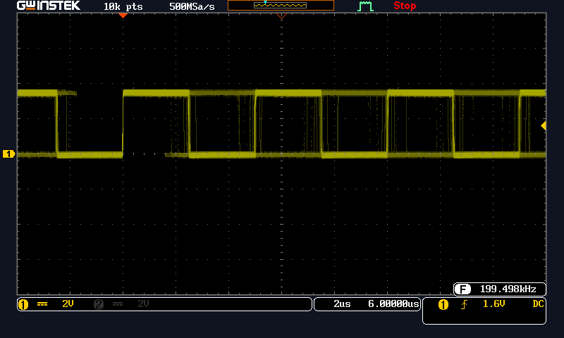
That's an unstable mess. There's over 500ns of jitter.
- Let's try unplugging the USB cable and run the board on battery power
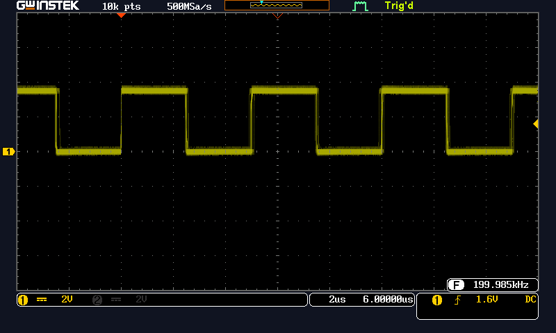
OK. That's better. The USB port firmware must be interrupting the tone() function. Lesson learned: Disconnect the computer for a stable output. Let's try using the USB A port on the oscilloscope for power. No, the output is unstable again. Let's try power from a cheap charger. That's stable again. I'm going to use battery power since it gives the cleanest results.
Try tone(7, 250000); Output was stable 250.0 kHz.
Try tone(7, 300000); Output was stable 300 kHz, without much jitter.
Above 300kHz is were things get strange.
tone(7, 301000) generated 303.8 kHz. Setting 302000 or 303000 also generated 303.8 kHz. The tone() function is likely using an integer divider from the peripheral clock. The divider resolution is not fine at these higher output frequencies. This causes coarse steps in output frequency. Maybe the tone() function can be improved, but this isn't going to replace an analog signal generator at 455 kHz.
Setting 304000, 305000 or 307000 all generated 307.7 kHz.
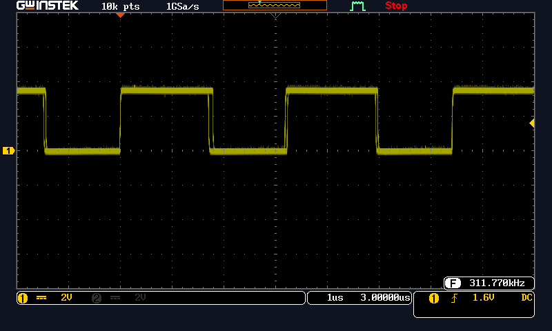
Setting tone(7, 308000); generated 311.7 kHz with some edge jitter.
Then the board stopped responding to the uploader in the Arduino IDE. The square wave signal continued, but new code could not be written. This may be an on-chip issue or a bug in the library. The USB port was not functional. The IDE reported "no device found on ttyACM0". Fortunately this board has a nice USB bootloader. The following sequence worked to restore normal operation:
- double click the reset button
- mount the ITSYBOOT partition as a USB drive
- copy any valid .UF2 file into the partition. I used a CircuitPython UF2 file from the Adafruit repo
- The circuit python partition now appears. Unmount this and reset the board again.
- Now Arduino IDE can upload and overwrite the CircuitPython with new code.
I did this several times to confirm the tone() settings that caused the port to lockup. Let's try a higher frequency.
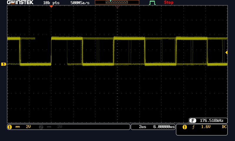
Setting tone(7, 350000); generated 176.6 kHz with bad jitter.
Setting tone(7, 390000); generated 196.7 kHz with some edge jitter.
In summary
- Disconnect USB data signals for a stable output. The USB driver on the M0 board seems to mess with the tone() function.
- Don't try setting an output over 300 kHz as this risks locking the USB serial port.
- Frequency setting near 300 kHz has coarse steps of more than 3 kHz (>1%). This isn't useful for generating a sweep signal.
- The tone() function goes higher than expected, but only for certain frequencies. Checking the library code or calculating the integer divisors is a task for next time
Discussions
Become a Hackaday.io Member
Create an account to leave a comment. Already have an account? Log In.