 Quinn
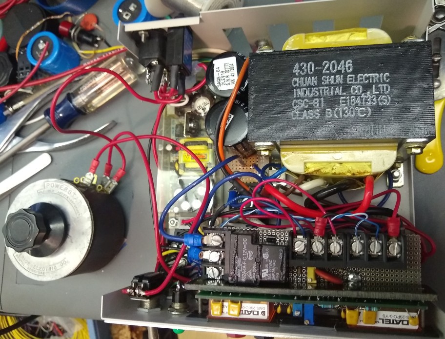
QuinnI wired it all up, which is a bit messy. The thicker 14 gauge stranded wire is part of it. But it'll work. I might need to put a divider in to keep the wiper on the bottom of the variac from tangling in the wires. The schematics as before reflect what was implemented.
This all got assembled, only to find that when I changed the pcb size, I forgot to take into account the variac which is mounted on the top. As a result, it won't fit. So it'll need some adjustment. Cutting off part of the pcb with the relay and it's terminals will resolve this, and I can relocate these below.
Testing
While the variac doesn't currently fit, I could wire it and leave it off to the side to test.
Testing it out using an HP 6060A DC load, the output works as expected.
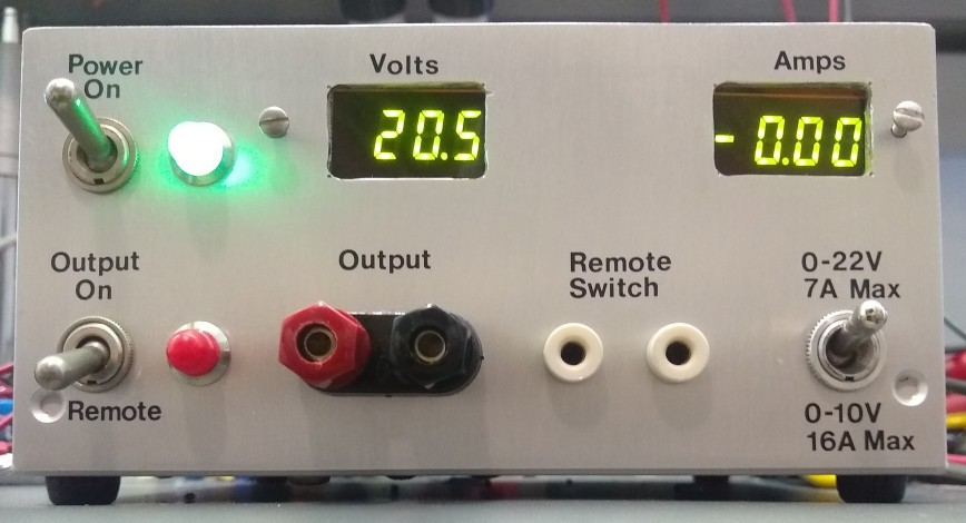
The only issue seen is that the current meter reads lower than real. I may have modified the board incorrectly, or it may require an increased smoothing capacitor. I measured the voltage off the shunt and it's correct, so there is something wrong with the meter or it's wiring. After some further debug I found there were 2 issues. There was an extra resistor on the meter circuit board which was causing a divider with my series 1K. Removing that fixed this. Also, the caps on the meter circuit were not sufficient, and a larger one was required to smooth the ripple.
The case bottom can get quite hot at higher current outputs due to the bridge. The thermal pad seems to work well, though the case bottom ends up substantially hotter than desired. A minute at max current and it becomes too hot to touch. I'll proceed as is, and will make a note of it on the case to take care with during use. Rarely will the high current be needed, and even then the will be breaks between cuts to allow cool down. The only other options would be to add forced air cooling, or relocate it to support an external heat sink.
Heat from the shunt doesn't seem to be an issue.
Edit: turns out it wasn't the cap on the current meter input that was the problem. It was much trickier than that. Hidden on the meter circuit board, underneath the meter module was a trace connecting the IN- to analog common. The name of the latter is misleading and in most situations this pin must be left no connect. It's ok to connect in this way only if the input is completely isolated from the meter supply. In my use, I was connecting IN- to the low side of the shunt, which was in turn connected to the supply negative. The manufacturer even has an application note detailing the trouble with this.
As the trace was under the meter, I was able to carefully find it by shining a light under the edge and seeing the trace through the pcb. I then drilled carefully through the pcb to sever the trace, but not drill into the meter module. I had to use a fly wire to wire it as needed. Then, finally, the meter worked correctly.
Discussions
Become a Hackaday.io Member
Create an account to leave a comment. Already have an account? Log In.