 StanleyProjects
LedBox V2 is a fully contained, sound reactive, ESP32 based module for controlling 5-12V addressable LED strips (WS2812, SK6812, etc.), supporting both 3-(VDD,DAT,GND) and 4-(VDD,DAT,CLK,GND) pin configuration.
The module has a dedicated step-down converter, which allows to seamlessly use it with both 5V and 12V strips (input voltage needs to match strip's voltage). It also contains a digital MEMS microphone, side button, 32kHz IR receiver, 10A safety resettable fuse, 1000µF buffer capacitor, 3.3V/5V level converter for both Data and Clock lines, together with an impedance matching resistor. These features ensure maximum functionality, safety, and led strip compatibility, all in a small (54x32x18mm) 3D printable enclosure.
Writing your own firmware is option which unlocks limitless possibilities, but to avoid reinventing the wheel, the module is by default fully compatible with WLED and Sound Reactive WLED firmware for Wi-Fi control.
Specification
The 5.5x2.1mm, center-positive DC barrel jack allows MAX 17V input voltage (VDD_IN), determined by TPS62162DSG step-down converter. However, since VDD_IN is directly connected to LED strip's power supply (VDD) through a resettable fuse (PPTC), be very careful, and connect only voltage that is rated for your LED strip (usually 5V or 12V). Also, make sure that the power capabilities of your supply meets (or preferable exceeds) the expected power requirement of the LED strip.
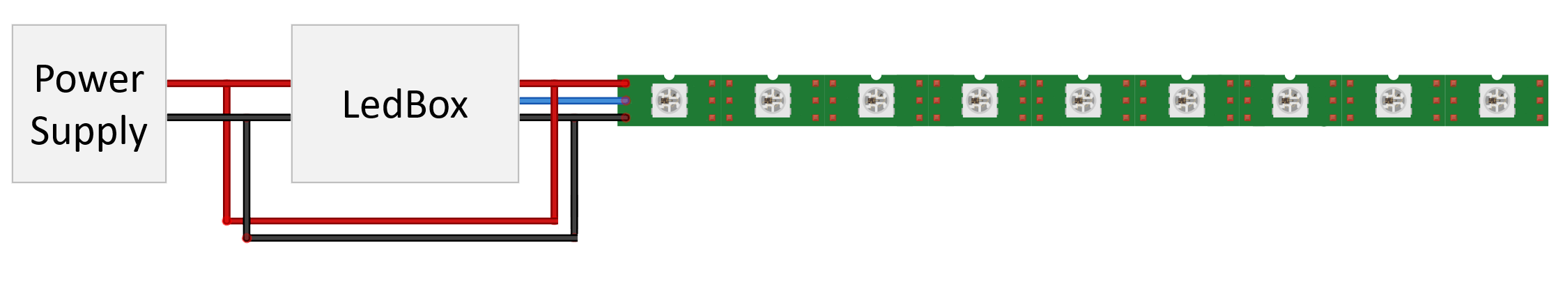
The LED strip is connected through a safety resettable fuse (PPTC) which will trip if the current draw exceeds 10A. This feature can be bypassed by closing the JP2 solder bridge on the back side of the board, but it is not recommended due to safety reasons. The main function of the fuse is to protect the module in scenarios like short circuit on the strip side. I strongly advise against running the module close to 10A. Keep in mind that even the JST SM connector, that addressable LED strips use, is officially rated only for max 3A. If you really need to power strips with higher current consumption, a safer way is to branch out the power line (VDD, GND) before the module using thicker cables, and connect them directly to the strip (power injection).
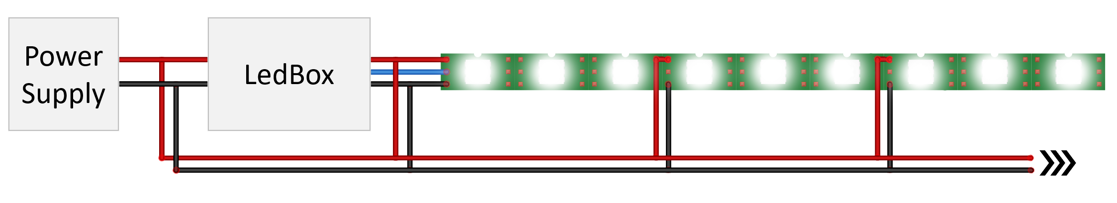
When using longer strips (>5m), you might experience a color shift towards the end, due to the voltage drop caused by strip's resistance.

This can be also solved by injecting power directly to the strip, but it needs to be done for every few meters.
Always make sure that you know and understand what you are doing, especially when dealing with large current. You are doing this at your own risk.
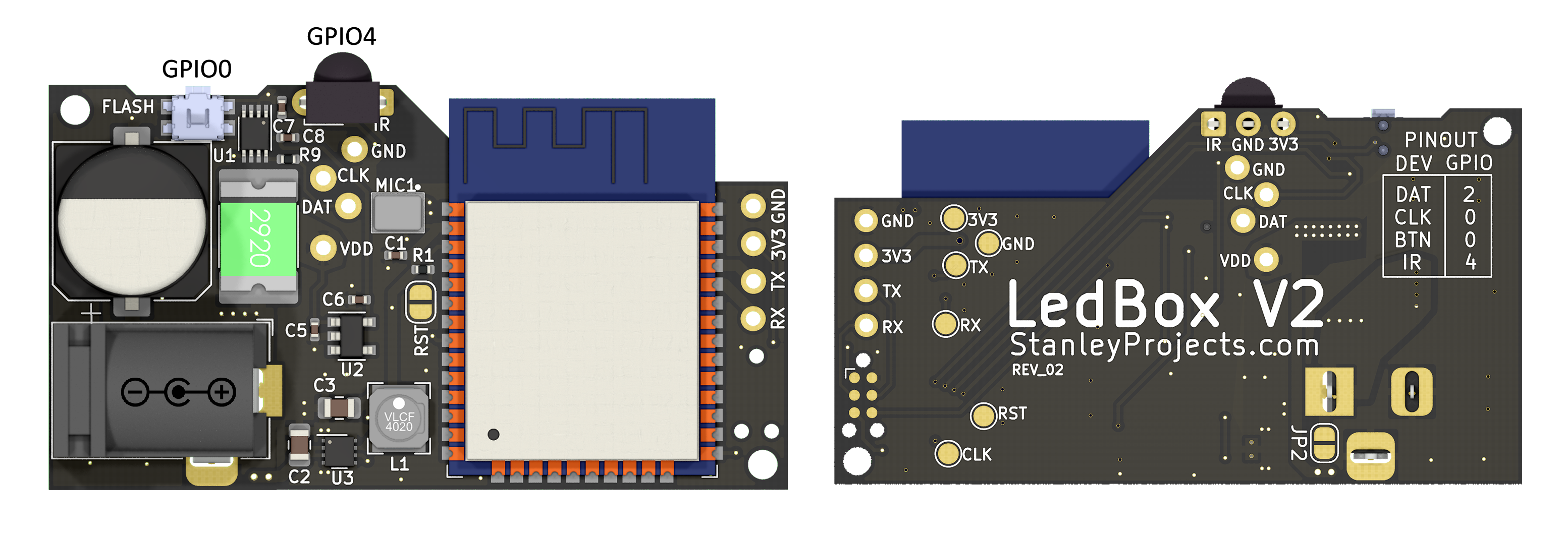
LedBox comes with a standard 3-wire JST SM connector soldered on VDD, DAT, and GND, for seamless connection of 3-pin addressable LED strips. To use 4-wire strips, additional CLK pin can be easily soldered. DAT has a 470Ω series resistor, and both DAT and CLK are bi-directionally level-shifted from 3.3V to 5V by TXS0102DCU, to meet recommended operating conditions for most strips.
| Device | GPIO | Notes |
| DAT | 2 | LED Data |
| CLK | 0 | LED Clock (not used by default) |
| BTN | 0 | Control / Flash button |
| IR | 4 | 32kHz demodulator |
| MIC | 14/15/32 | Digital SCK/WS/SD |
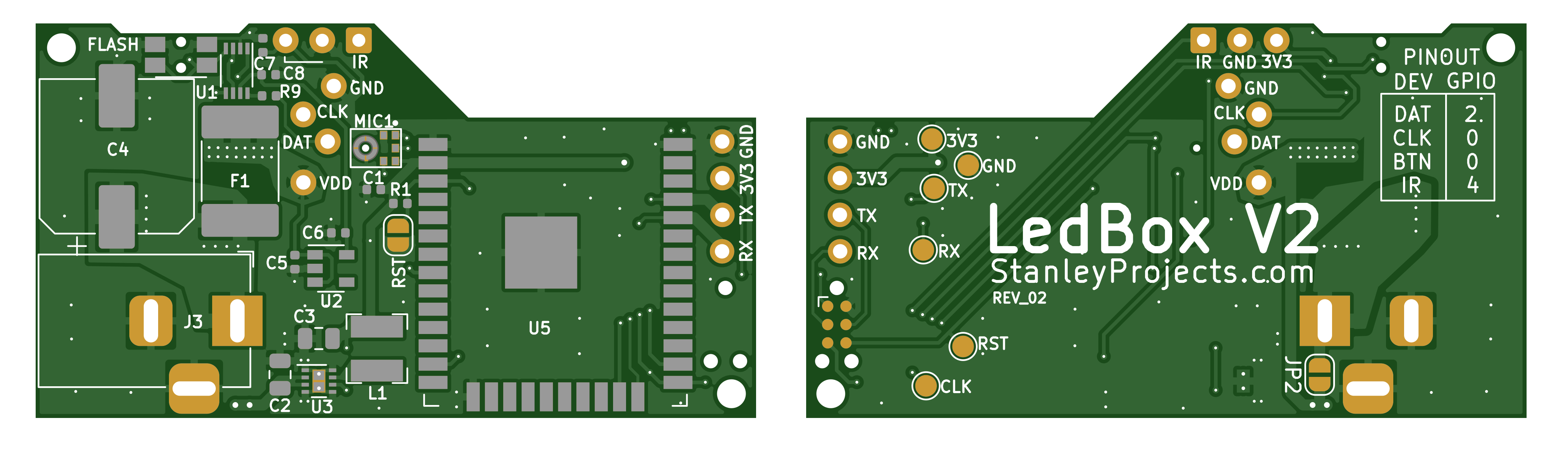
Purchased module comes with preloaded sound-reactive WLED firmware and works out of the box. Moreover, WLED has the ability to perform over-the-air updates (OTA), such that you can upload the compiled .hex file directly through browser interface, and the module automatically updates its firmware. However, if you still want to flash the ESP32 yourself, an external serial-to-usb adapter such as notoriously known red FT232RL FTDI board, is needed. The adapter needs to be set to use 3.3V (5V would destroy the chip), and connected as shown in the picture below.
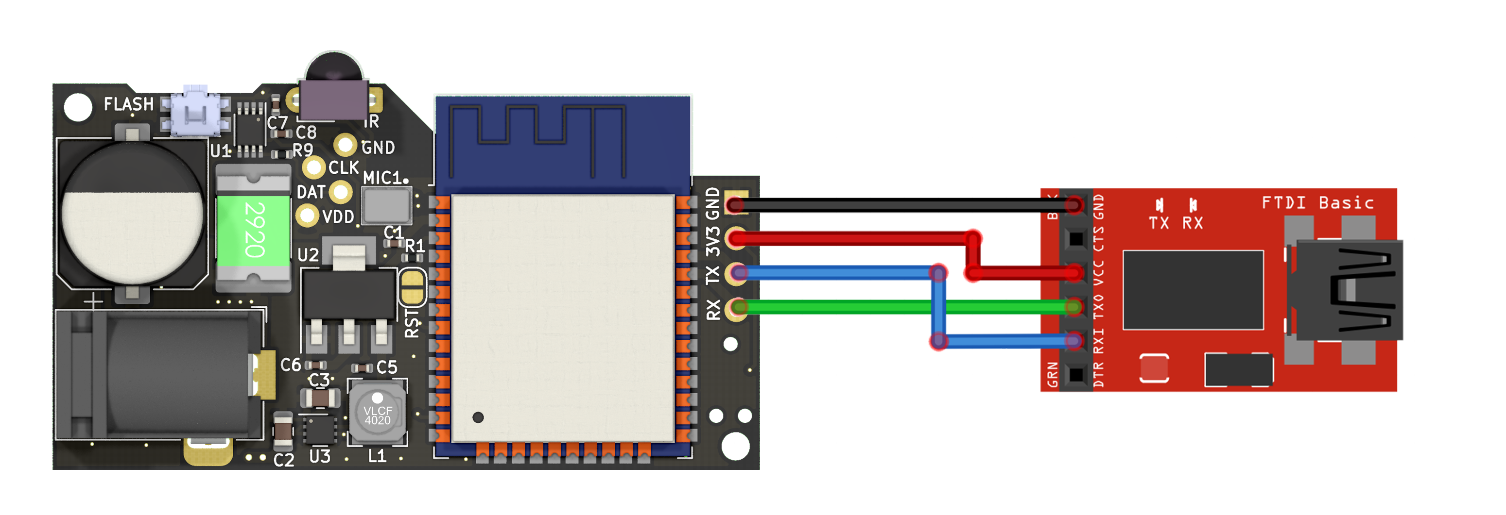
After connecting the programmer, the chip needs to enter bootloader mode. This can be done by pressing the "FLASH" button, resetting the chip by shorting "RST" bridge or reconnecting 3V3, and then releasing the button. Now it is ready to be flashed with a new firmware. If the chip does not boot after flashing, you might have to flash esp32 bootloader to memory address 0x0. See more details here.
The board also has test pads and Tag-Connect on the bottom for programming and testing in a jig, which is available on project's GitHub.
Specification
To fully utilize module's potential, it is recommended to use the sound-reactive version of WLED firmware. Since this firmware has disabled IR by default, LedBox comes with a modified version, which enables all supported features. This firmware is available to download in the right sidebar under "Resources".
When you first boot the module, it is important that you setup the required functionality in WLED's settings.
In Config > LED Preferences, set Button pin: to 0, IR pin: to 4, and press Save.
In case you want to use the IR interface and it still does not work, you might have one of the earlier version of the board, that came with the default firmware.
To fix this issue, simply navigate to Config > Security & Updates > Manual OTA Update, click Choose File, select the newest firmware (LedBoxV2_SR_WLED_*.bin), and click Update.
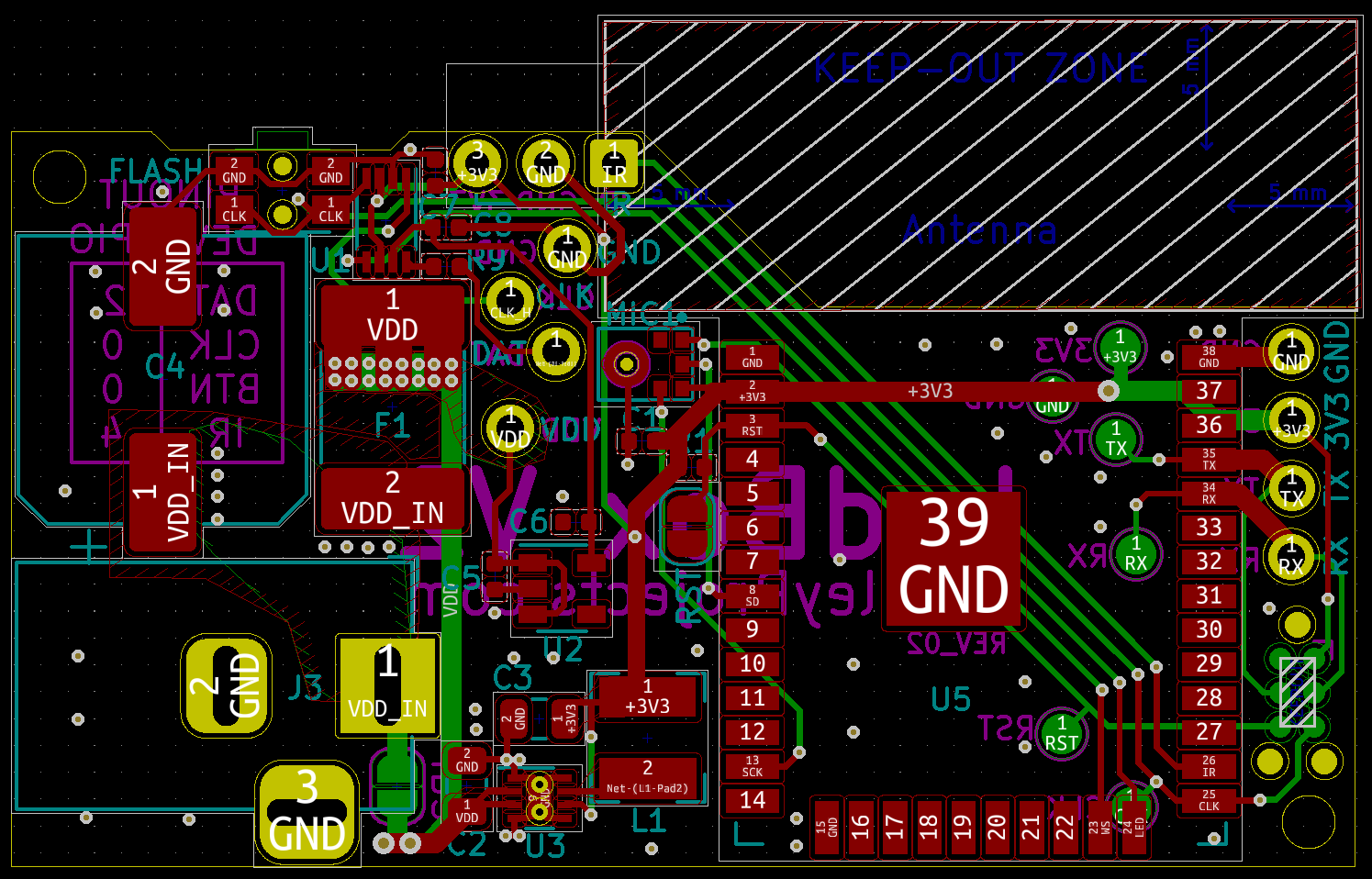
Layout
More information