 Joseph Eoff
I long ago decided that the control nodes would need to be powered from a fairly large battery, that they needed to be solar charged, and that building a solar charging system for a large lithium ion battery was not part of this project.
I spent most of my free time this weekend making a set of adapters to hold the ESP32 modules.
Each adapter has an LM3671 buck regulator module, a voltage divider so the ESP32 can monitor the battery voltage, and a switch so I can turn off the power and remove the ESP32 from the adapter.
There's nothing special about them - some perf board, a couple of resistors and a capacitor, a regulator module, and a switch.
One thing I did do, though, was to build them so that I cannot connect the module to a USB cable while it is plugged into the adapter - I'm pretty sure that powering them from the LM3671 and USB at the same time would cause a mess, so I blocked it to keep me from getting stupid ideas.
Most of the last log posts have been rather text heavy. This one will be mostly pictures.
Beginning
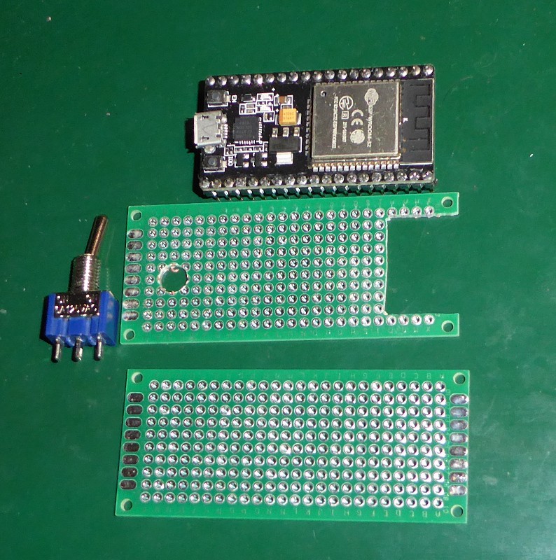
The cutout on the right end is to reduce the amount of metal near the ESP32 antenna.
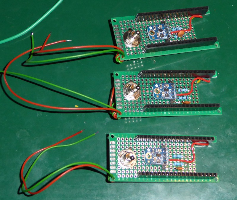
Finished adapters:
With the adapter finished, I attacked the solar charging power banks.
Power bank:
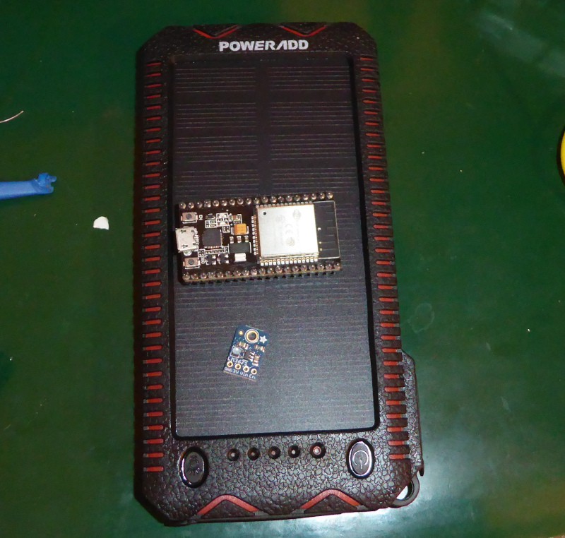
You may recognize that image if you've been following the logs and my blog.
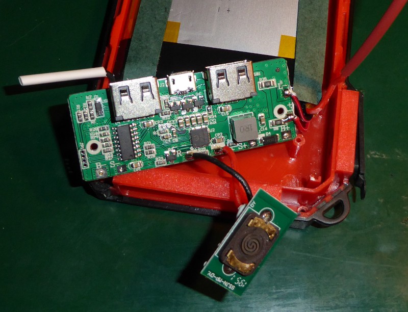
Once you take it apart, you find this:
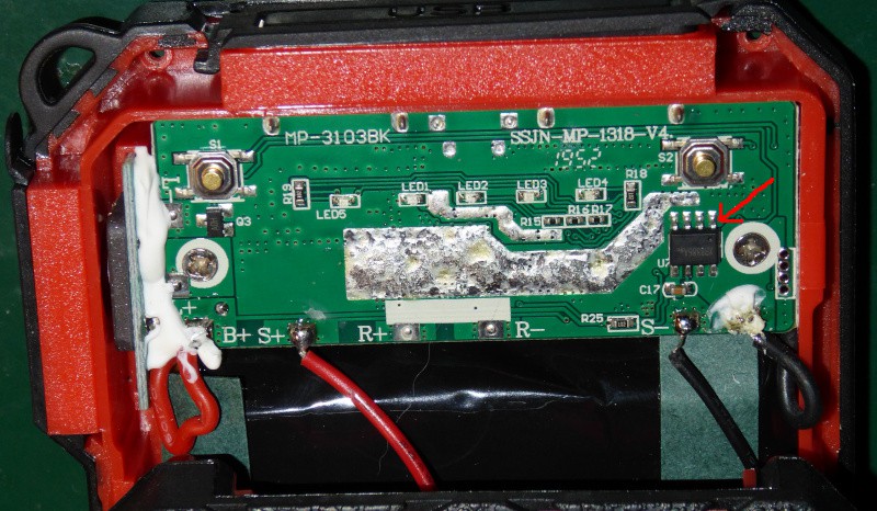
The red arrow points to the XB8886A battery protection IC. If you are modifying a power bank, you need to find the battery protection IC, and make sure that you connect to the correct side of it. You want it to be able to disconnect your additional circuitry as well as the existing circuitry. The XB8886A disconnects the ground. Pins 1,2,3,4 are the "safe" grounds. You connect your load to the battery positive terminal (B+) and to the those pins and the lithium ion cell will be protected from your circuit - that's short circuit and low voltage.
Working on a power bank is like working on the electrical system of car. You always disconnect the ground wire first.
That's the unmarked, thick black wire on the right side. With it disconnected, you can't accidentally short the battery and blow things up.
The battery ground is also the last wire you reconnect.
Since this battery bank is solar powered, the next wire to disconnect is the solar cell negative terminal. That's the black wire marked "S-".
With the grounds disconnected, it is safe to work on the positive wires - there's no place they can cause a short if you bump something.
"R+" is the lighter coil power connection. I removed the lighter coil (the white blob on the left side,) then used the "R+" pad to connect my PTC and the run a wire to the outside for the ESP32.
My PTCs are rated to supply 900 milliamperes continuous, and trip at around 1.5A. That's more than an ESP will need, but still low enough to be safe.

That's everything disconnected. I'm something of a chicken, so I stuck pieces of heat shrink tubing over the battery wires to prevent accidents.
This is the lighter coil:
I removed it. My control nodes don't smoke cigarettes, so they don't need lighters - but I do need the hole in the housing to put my wires through.
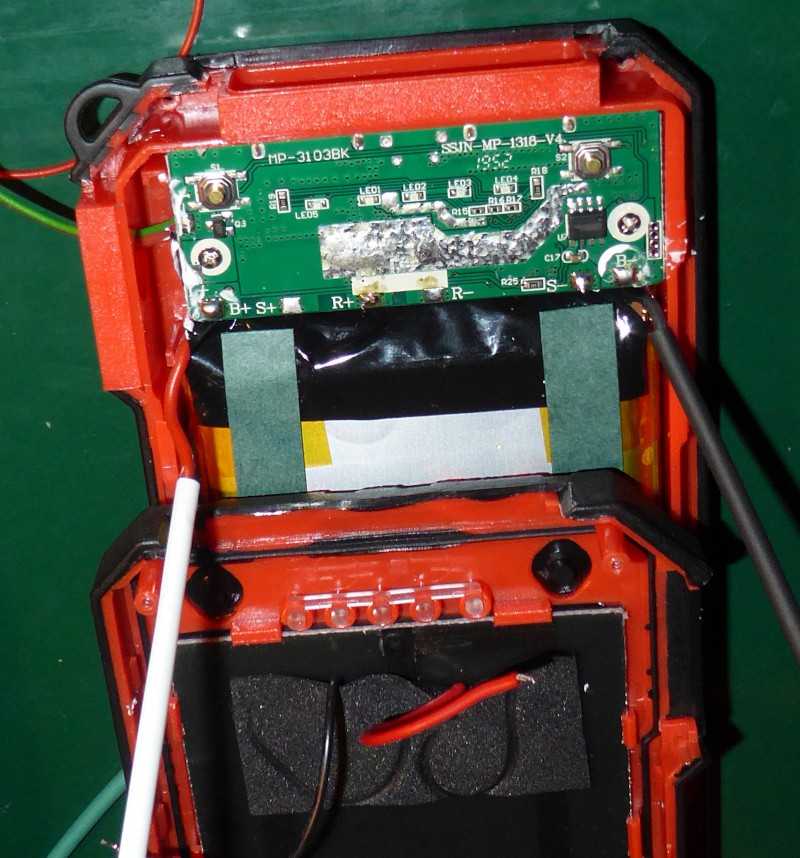
Here's the PCB with my wires added:
I've tied the new red and green wires around the screw post to keep them from pulling out, and hot glued the wires in place (not in this picture.) You can't see it, but the red wire connects to a PTC that is soldered to the "R+" pad. The green wire goes to the "S-" pad - that's the solar cell negative terminal. It's on the correct side of the protection circuit and isn't switched.
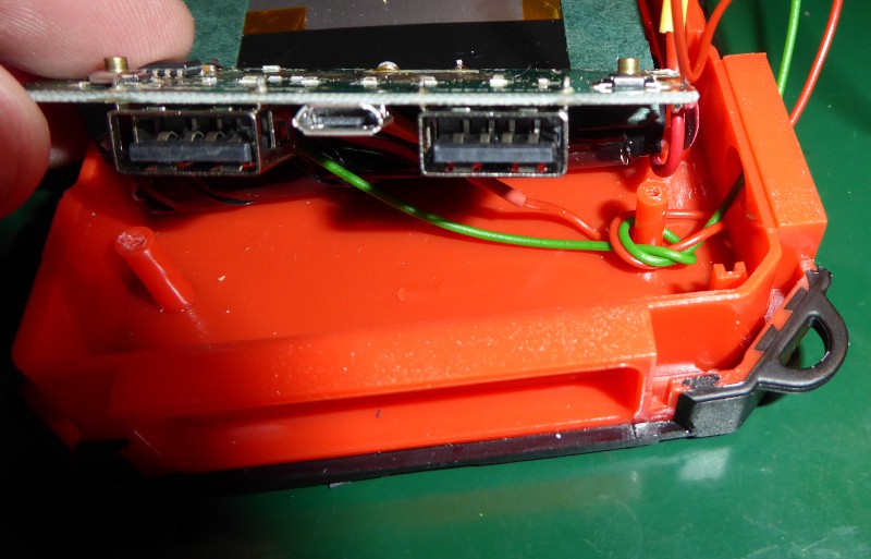
Modifications complete, ready to be reassembled:
Again, you do this like you do a car battery: positive terminal first, then ground.
Here's a completed power bank with an ESP32 and an adapter:
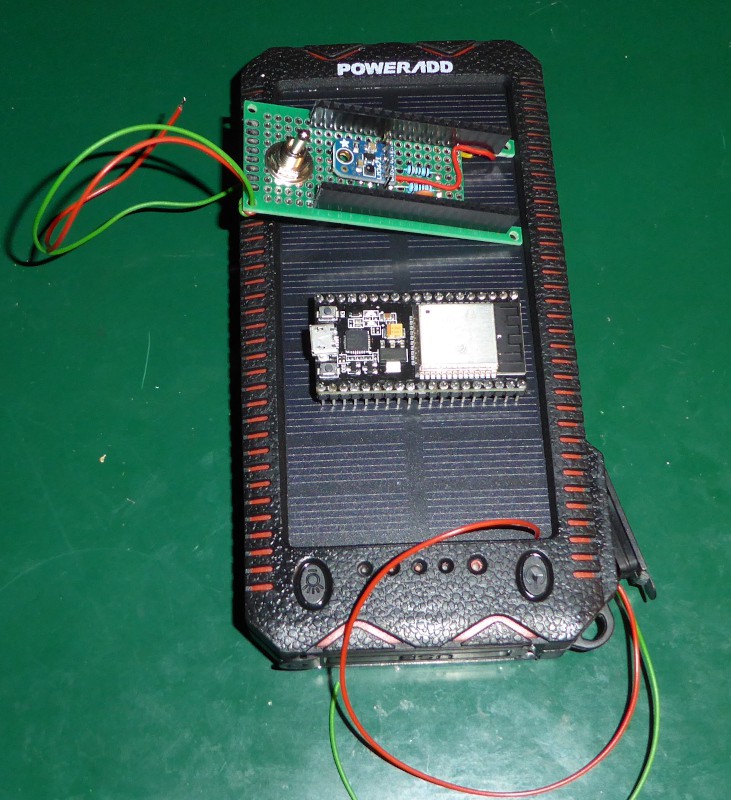
I haven't connected them together. The adapter needs some strategically placed daubs of hot melt glue as insulation on several points, and the lighter port on the power bank needs to be filled as well. I'd have gone ahead and done it, but I've run out of hot melt glue.
I'll start work on the ESP32 software this week, and (with a little luck) be ready to put things out in the yard next weekend.
Discussions
Become a Hackaday.io Member
Create an account to leave a comment. Already have an account? Log In.