Keith
KeithIn the original board, based on the circuit in the data sheet , VPP sometimes glitched high at power-up and write garbage to the EPROM.
This design fixed the problem by driving the base of Q2 from the reset chip. At power-up, TR4 is 'off' and no current can flow through TR2 emitter. So TR3 cannot switch on during reset.
The red wires on the underside are not a bug fix. I merely wanted access to those signals for an experiment and taking them to the connector was the most convenient way to do so.
 Jeremy g.
 John Whittington
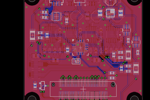
 Pinski1