Do you like to watch combat robot championships? The best of all is in the great dispute between the participating robots. They fight for their teams to be winners and seek to eliminate the participants of the enemy team.
The championship is perfect for encouraging players to build strong and competing robots. However, many people have questions about how to build their competition robots and how to create the rules for the game to work.
The championship is perfect for encouraging players to build strong and competing robots.
However, many people have the following doubts:
- How to build your competition robots,
- creating a robotics championship
- development of the rules to make the game work.
From now on we will answer all these questions by building the ARGUS Robot. After all, who is Robot Argus?
The ARGUS Robot History
ARGUS are robots that have lived on earth for many years. Thousands of years ago they were created to assist historians in the search for ancient artifacts. It is from a family of robots that look like ants, meaning they don't work alone. They are very collaborative with each other and dependent on each other.
In addition to using their mini guide to hunt, they can use them to defend themselves from enemies.
You should never have just one ARGUS Robot. You need two or more because while the first is working the second will protect him.

ARGUS is known to be tiny and agile robots. In a short time they are able to find good artifacts, take them to the support bases and keep them safe from enemy pirates.
Let's go on the hunt and understandthe ARGUS structure and how to program ARGUS to capture artifacts?
The ARGUS Robot Structure
The ARGUS robot can work autonomously or remotely controlled via commands sent via Bluetooth.
Autonomous operation
In its autonomous mode, ARGUS is used to avoid obstacles through the use of the ultrasonic sensor. He is able to navigate in any environment.
Remotely controlled
This mode is used to create competition between several ARGUS. In this mode, you need to use an application on your cell phone or a wireless controller to have ARGUS collect all the artifacts and take them to a safe place.
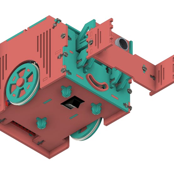
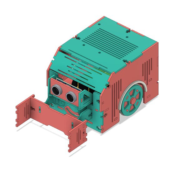
Next, we'll present the complete structure of the ARGUS Robot.
ARGUS uses an Arduino UNO as the control board for your entire system.
The Argus is a robot designed to have the characteristic of a toy. Most of the toys have a system to turn on and off with a button on the bottom of the robot floor.
This structure was implemented and added to the body of ARGUS. See the figure below and observe the structure of the aforementioned button.
The ARGUS is powered by a 7.5V / 2.6Ah battery. This battery energizes the entire system and allows the ARGUS to run for 3 hours and 30 minutes.
This time is sufficient for him to participate in any competition.
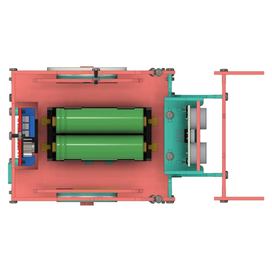
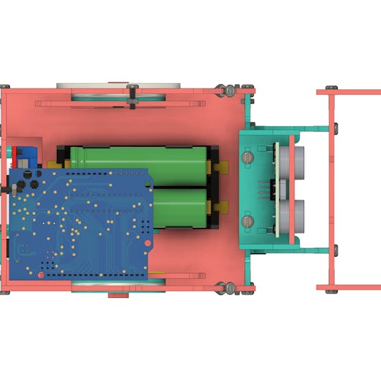
The battery is responsible for powering the Arduino and the wheel motors. The Arduino is responsible for all navigation control of the robot.
It reads the ultrasonic sensor, receives user commands, and activates the robot's motors. The motors are the most used elements that need the most energy consumption in the project. For this reason, we created a space for the installation of 2 LiPo 18650 batteries.
See the circuit presented below with Arduino Board and Battery.
In addition to the Arduino UNO, we provide an Arduino for you to download and assemble your project. You just won this Arduino!
Use the JLCPCB Arduino Compatible printed circuit board presented below.
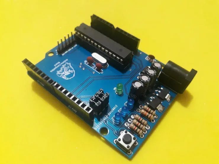
You can obtain the Arduino JLCPCB compatible PCB for your projects for $2 in your first order with the link: Earn my PCBs Arduino Compatible.
Use the JLC-RECE coupon,earn a $2 off discount, and earn FREE5 PCBs.
ARGUS has access to the Arduino UNO's USB port. This allows the programming of the robot without the need to remove the Arduino Board from the inside of the robot.

After you have seen and learned how the ARGUS structure works, it is time to learn how to create a programming logic for it to work.
Development of programming logic for autonomous mode
In this first project, you will learn how to make ARGUS avoid obstacles. ARGUS will move around the environment alone and dodge anything in front of you.
Take great care of him. He can run away from you and go!
To make this code you must assemble the electronic circuit shown in the figure below.
How does it all work? Shall we understand?
The circuit is quite simple and easy to understand. For this project we developed the code presented below.
#define Motor1A 2#define Motor1B 3#define Motor2A 4#define Motor2B 5#define echoPin 9#define trigPin 8long tempo = 0;byte distancia = 0;void setup() { Serial.begin(9600); pinMode(Motor1A, OUTPUT); pinMode(Motor1B, OUTPUT); pinMode(Motor2A, OUTPUT); pinMode(Motor2B, OUTPUT); pinMode(echoPin, INPUT); pinMode(trigPin, OUTPUT);}void loop() { digitalWrite(trigPin, LOW); delayMicroseconds(2); digitalWrite(trigPin, HIGH); delayMicroseconds(10); digitalWrite(trigPin, LOW); tempo = pulseIn(echoPin, HIGH); delay(300); distancia = tempo * (0.034/2); Serial.println(distancia); if(distancia >= 10) { frente(); } else { parar(); delay(500); direita(); delay(1000); parar(); } }void frente(){ digitalWrite(Motor1B, LOW); digitalWrite(Motor2B, LOW); digitalWrite(Motor1A, HIGH); digitalWrite(Motor2A, HIGH);}void re(){ digitalWrite(Motor1A, LOW); digitalWrite(Motor2A, LOW); digitalWrite(Motor1B, HIGH); digitalWrite(Motor2B, HIGH);}void parar(){ digitalWrite(Motor1A, HIGH); digitalWrite(Motor2A, HIGH); digitalWrite(Motor1B, HIGH); digitalWrite(Motor2B, HIGH); }void direita(){ digitalWrite(Motor1B, LOW); digitalWrite(Motor2A, LOW); digitalWrite(Motor1A, HIGH); digitalWrite(Motor2B, HIGH);}
In the first step, we define the pins used by the motors, ultrasonic sensor, and the program variables. See the code portion below.
#define Motor1A 2#define Motor1B 3#define Motor2A 4#define Motor2B 5#define echoPin 9#define trigPin 8long tempo = 0;byte distancia = 0;
In the setup function, we configure the pins as inputs and outputs based on how they will be used in the code.
void setup() { Serial.begin(9600); pinMode(Motor1A, OUTPUT); pinMode(Motor1B, OUTPUT); pinMode(Motor2A, OUTPUT); pinMode(Motor2B, OUTPUT); pinMode(echoPin, INPUT); pinMode(trigPin, OUTPUT);}
Now let's understand the main logic in the loop function.
void loop() { digitalWrite(trigPin, LOW); delayMicroseconds(2); digitalWrite(trigPin, HIGH); delayMicroseconds(10); digitalWrite(trigPin, LOW); tempo = pulseIn(echoPin, HIGH); delay(300); distancia = tempo * (0.034/2); Serial.println(distancia); if(distancia >= 10) { frente(); } else { parar(); delay(500); direita(); delay(1000); parar(); } }
First, a code block was created to read the ultrasonic sensor. See the code below.
digitalWrite(trigPin, LOW); delayMicroseconds(2); digitalWrite(trigPin, HIGH); delayMicroseconds(10); digitalWrite(trigPin, LOW); tempo = pulseIn(echoPin, HIGH); delay(300); distancia = tempo * (0.034/2);
This code portion is used to trigger the sensor, receive the echo signal, and calculate the time.
From the time, the Arduino can calculate the distance between the ARGUS and any obstacle in front of it.
After that, it's time to check for an obstacle. This is done through the conditions below.
if(distancia >= 10) { frente(); } else { parar(); delay(500); direita(); delay(1000); parar(); }
The Arduino checks whether the distance is greater than or equal to 10. If this is true it means that there is no obstacle in front of the robot, and it will be moved forward.
The function responsible for activating the wheels in the forward direction (clockwise direction) is shown below.
void frente(){ digitalWrite(Motor1B, LOW); digitalWrite(Motor2B, LOW); digitalWrite(Motor1A, HIGH); digitalWrite(Motor2A, HIGH);}
In addition to this situation, we can have the indication of an obstacle when the distance is less than 10 cm. In that case, the following command block will be executed. See the code portion below.
{ parar(); delay(500); direita(); delay(1000); parar(); }
The Arduino stops the 2 motors, waits 500 ms, turns the robot to the right, and stops the robot again.
After that, the code flow goes back to the beginning, performs a new reading, and makes a new decision. If there is no more obstacle, the robot will move forward. Otherwise, the robot will rotate to the right again.
This is how programming logic works for the autonomous operating mode.
In the next article, we will explain how ARGUS works in artifact rescue mode. In the next article, we will teach you how to create the ARGUS app and control to rescue artifacts.
At this moment I ask that you leave your comment with doubts and like this text to let us know that you liked the story of ARGUS.
Acknowledgment
We thank Ludic Robot School and the company JLCPCB for offer support to create this project.
Use the JLCPCB Arduino Compatible printed circuit board presented below.
You can obtain the Arduino JLCPCB compatible PCB for your projects for $2 in your first order with the link: Earn my PCBs Arduino Compatible.
Use the JLC-RECE coupon,earn a $2 off discount, and earn FREE5 PCBs.