 Dominik Meffert
I started my work on the phase detection feature by reading the manual of a Videojet Excel 170i which I bought for testing. I read that it uses a 420us long 10VDC pulse for charging 28 droplets, which later get analyzed for selecting the right phase. This printer is using a piezo frequency of 66kHz which has a period of around 15us. 420 divided by 15 equals 28 which explains the numbers. This printer can select between 4 phase settings. It uses the gutter instead of a dedicated probe for reading the charge of the droplets. Unfortunately, it was not described how the printer analyzes the signal, so this did not help me much.
At least I learned from it that phase detection is an important part of CIJ printing and that it is done by sending a signal to the charge electrode which later gets read from the droplets to get a feedback system.
The remaining question at this point was, what a phase actually is and how the signal could help find out the right phase.
Fortunately, @Paulo Campos could help by telling me about an improved method that uses 16 instead of 4 possible phase settings and a phase detection sensor/probe instead of the gutter.
Thank you Paulo for helping me again :)
Now I had to implement Paulo's method into my DIY printer, which is no 1:1 copy of another printer, but my own design, so there was some work needed to get it going.
Phase Detection Signal Properties
The signal has to be a sequence of sixteen -12V pulses with each pulse starting with a different phase shift to the piezo's sine wave signal.
This is done to get 16 successive droplets each having a different phase shift setting. These droplets get analyzed by the printer to find out which droplet got the most charge from the -12V pulse for selecting the best phase shift setting, in short phase.
By doing so the printer can choose from Phase 1 with 0⁰ phase shift to Phase 16 with 337.5⁰ phase shift to get the best possible charging quality.
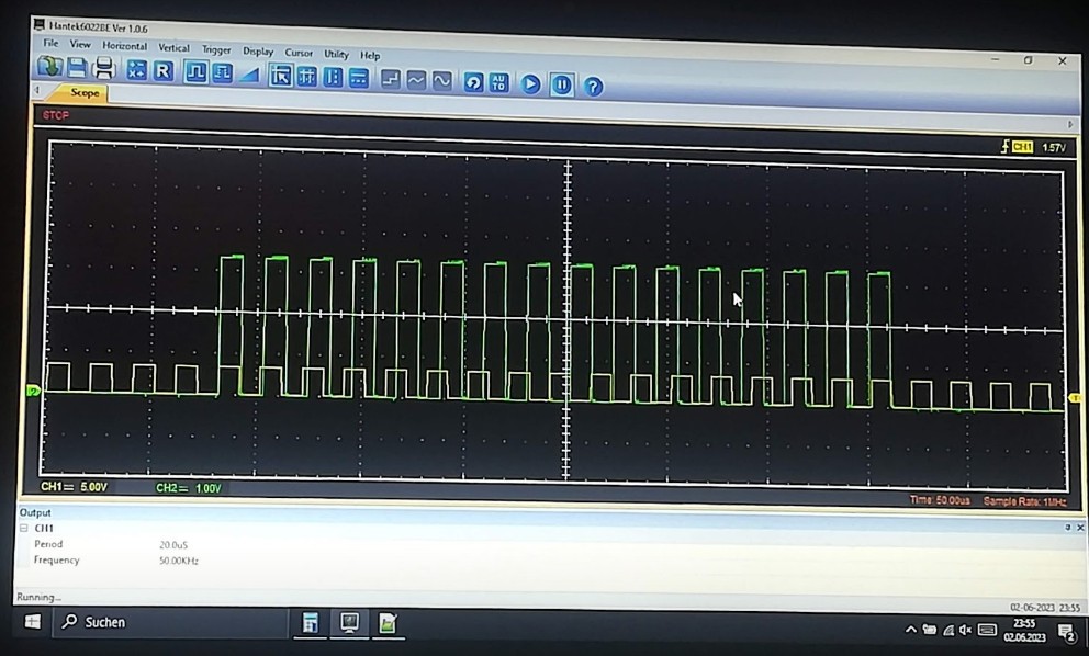
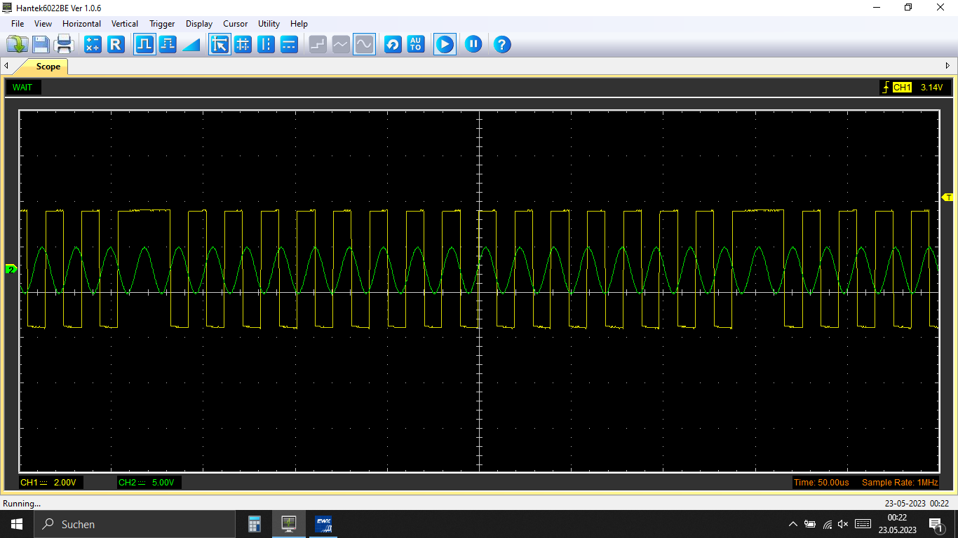
Piezo Signal
Starting with the sine wave that drives the piezo:
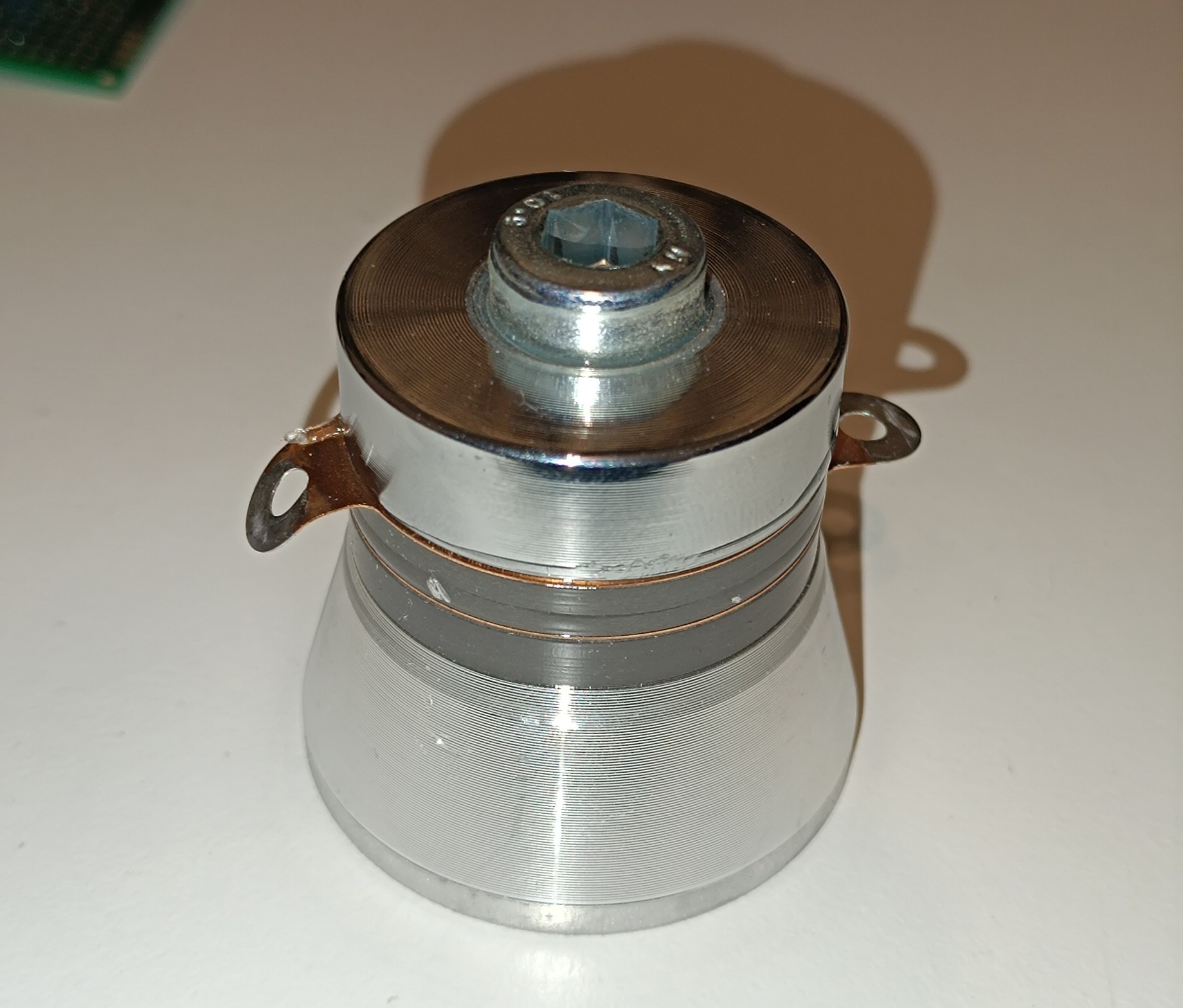
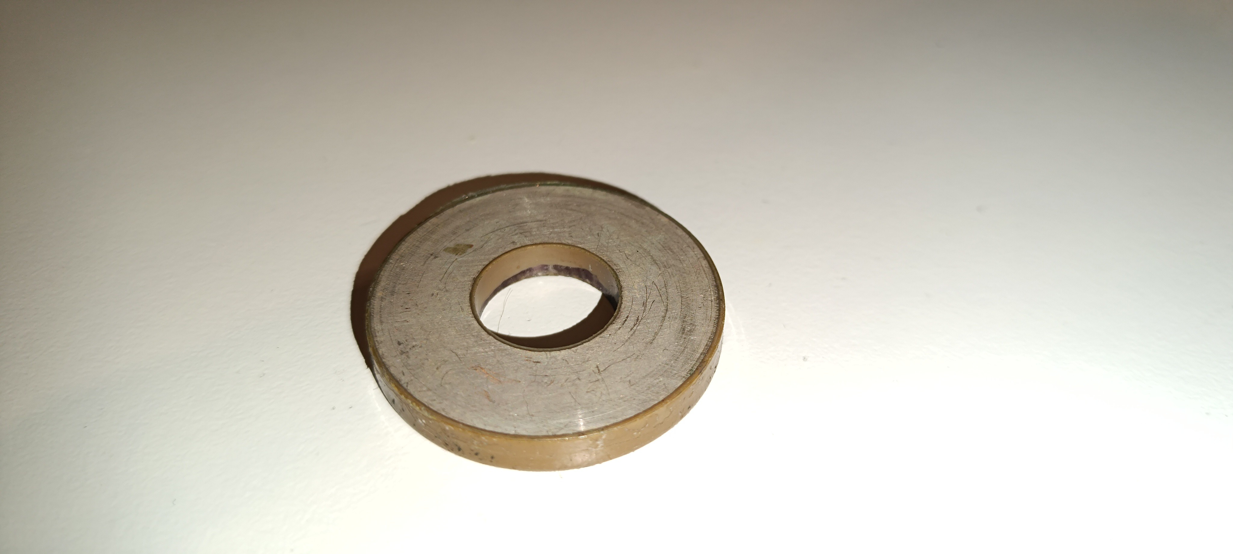
For my printer, I chose 50kHz for driving the piezo, because this frequency is compatible with the 40kHz piezo rings, that you can find in ultrasonic cleaners and because it has a period of 20us which makes calculations with it easier than using an odd number.
Before talking about the phase detection signal's waveform it's worth mentioning, that droplet formation happens over the whole sine wave period while on the other hand, the charging puls can be pretty short, but has to happen at exactly the right moment of the droplet formation process.
The phase detection feature finds the right moment by looking after the phase with the highest charge so that future charging pulses can be executed with this phase setting.
If parameters like ink pressure or viscosity change, the right moment for charging also changes which gets detected by the phase detection feature, which then selects another phase, that fits better to the new parameters.
Phase Detection Signal Waveform
Given that the piezo frequency is 50kHz with a period of 20us and the goal is to design a phase detection signal that completes a complete 360⁰ phase shift in 16 pulses I used a period of 21.25us for these pulses.
My assumption was:
20us / 16 = 1.25us
21.25us * 16 = 340us
20us * 17 = 340us
So, 16 pulse periods take as long as 17 sine wave periods which means that every pulse starts 1.25us later in the sine wave than the one before. The phase detection signal and the sine wave have to start at the same time and after 17 sine wave cycles / 16 pulse cycles, both waves are in sync again.
For the pulse, I just used a 50% duty cycle square wave, but I could just change the duty cycle if it turns out that another duty cycle would be better, just the period has to stay the same, so that 360⁰ phase shift takes 16 pulse cycles.
I added a 340us pause after the phase detection signal so that the period of the whole signal is 680us (340us signal, 340us pause) which equals a frequency of around 1.47kHz.
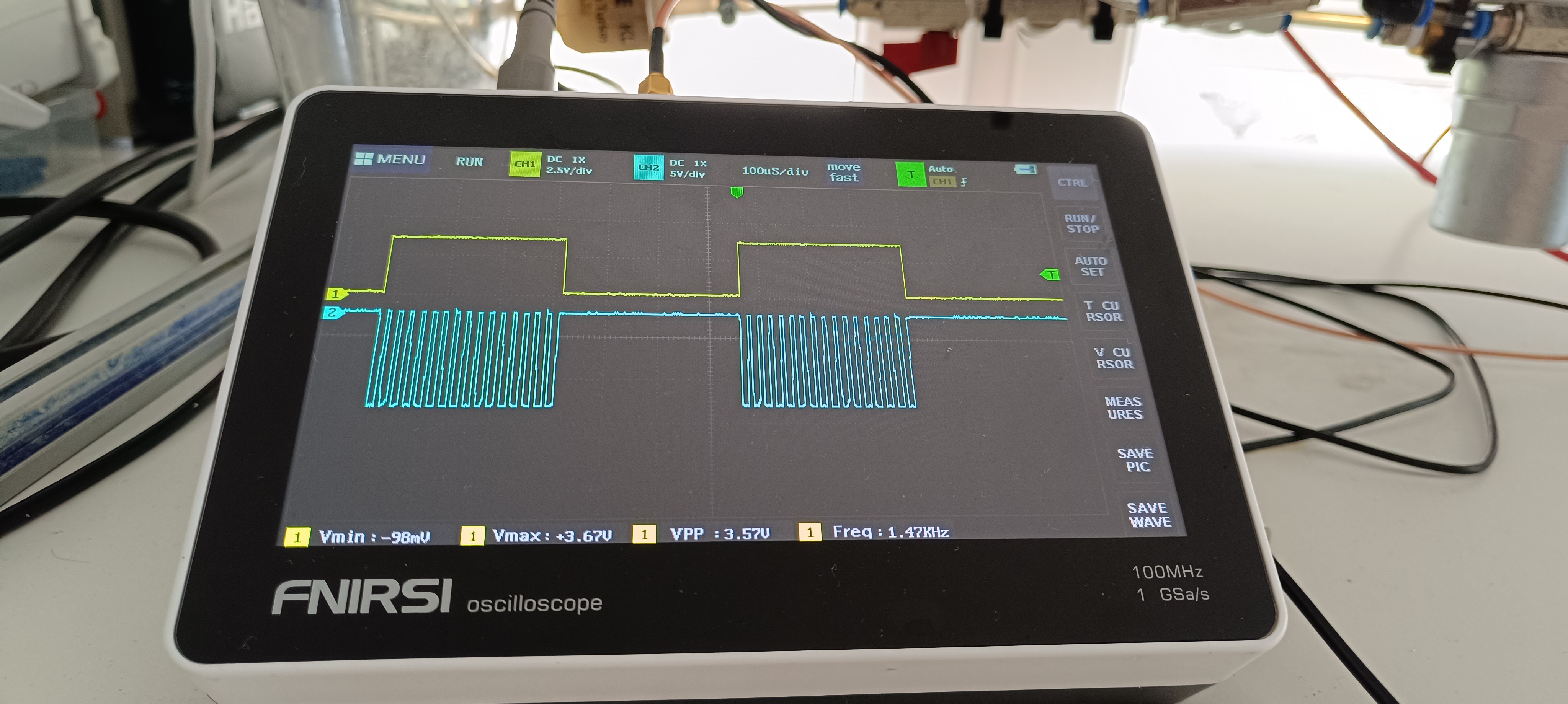
With that, the signal design was completed.
The next task was generating the signal which I will tell you more about in the next log.
Thanks for your reading :)
Discussions
Become a Hackaday.io Member
Create an account to leave a comment. Already have an account? Log In.