 Dominik Meffert
At the time when I started working on the phase detection signal generation, I used an AD9833 for generating a sine wave that drives the piezo and an LM393 Schmitt trigger circuit that converts it to a square wave, which drives the strobe LED that makes the droplet formation visible to the naked eye.
Unfortunately, this setup was not suitable for generating the phase detection signal, so I had to find another solution.
Commercial CIJ printers use FPGAs for their signal processing and generation, so I started by buying a beginner FPGA board - the BASYS 3.
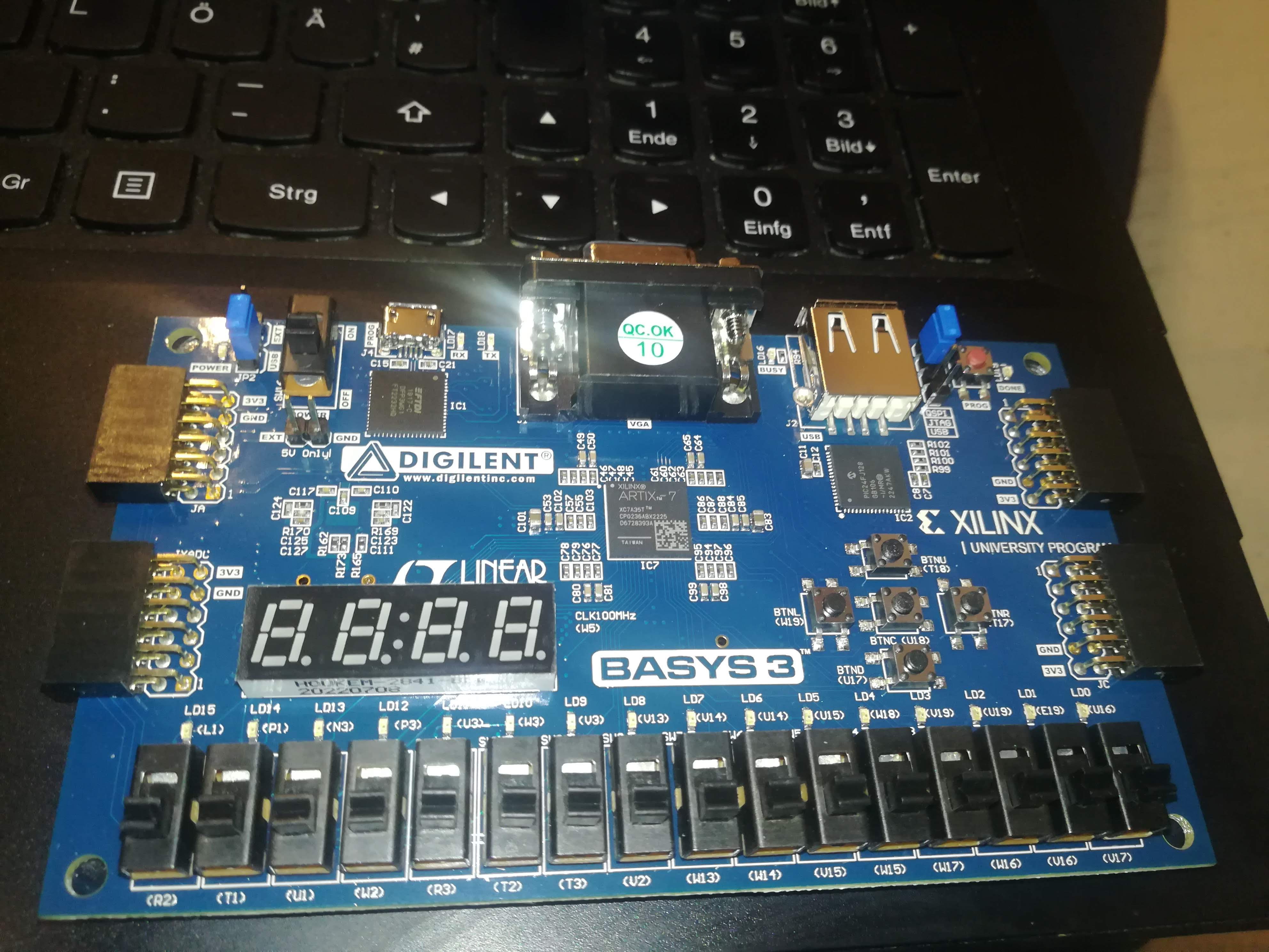
After trying out some tutorials and examples, I quickly realized that using an FPGA is not the best choice for a "low-cost, easy-to-build" open-source project, because of its cost and complexity.
So, another solution was needed.
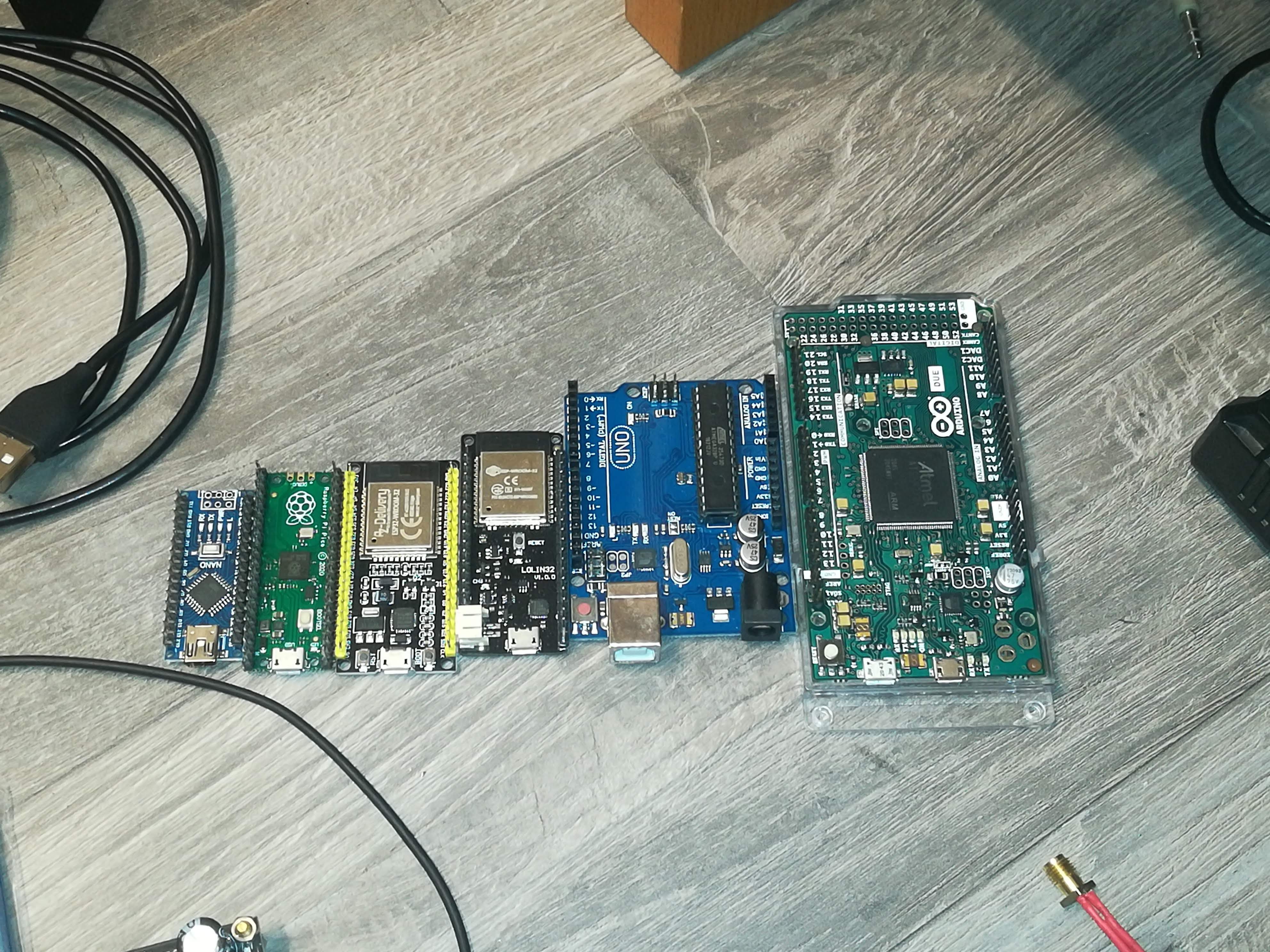
After the FPGA, I tried out multiple other microcontroller boards until I tried out the ESP32, which was able to generate pulse sequences like the phase detection signal with its RMT feature.
Unfortunately, I couldn't start different output channels at the same time with it. Even if there seems to be a synchronization manager feature for RMT, I couldn't find out how to get it working.
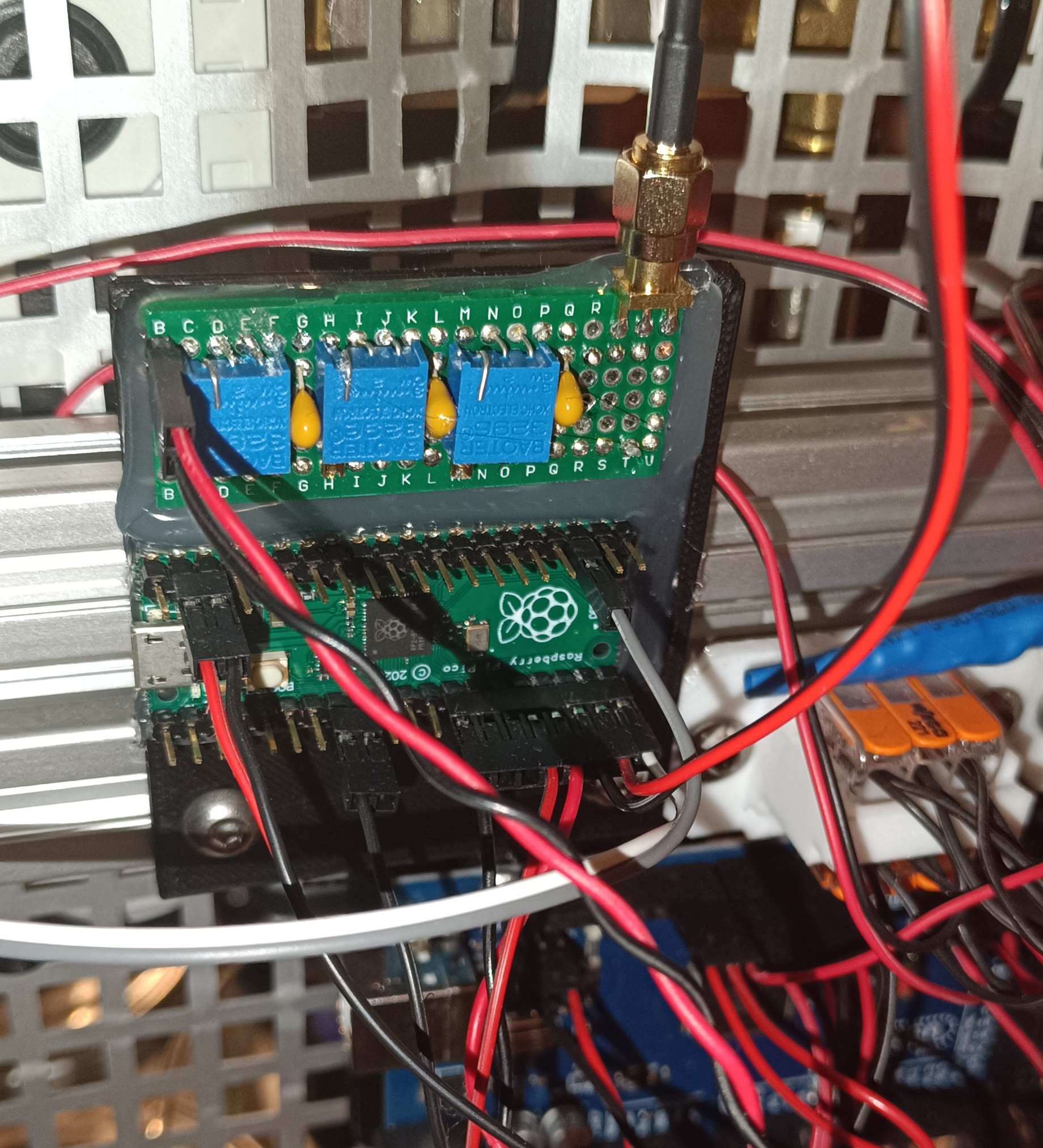
While searching on the web for infos about the ESP32's RMT feature, I read about the Raspberry Pi Pico's PIO (Programmable IO) feature, which turned out to be a better solution for signal generation than the ESP32's RMT feature.
The PIO feature of the Pico is intended to be used for coding your own communication interfaces to add functionalities to the Pi that it doesn't have out of the box.
The Pico features 8 so-called "state machines" with each of them being able to perform simple operations independently from the main CPU and other state machines.
They run a custom instruction set (no C++ or micropython) of which each instruction takes one clock cycle to be performed, which makes them ideal for time-critical tasks like communication or signal generation for this printer project.
They also can be synchronized, so that all signals needed for the printer's operation can have the same clock source and starting time.
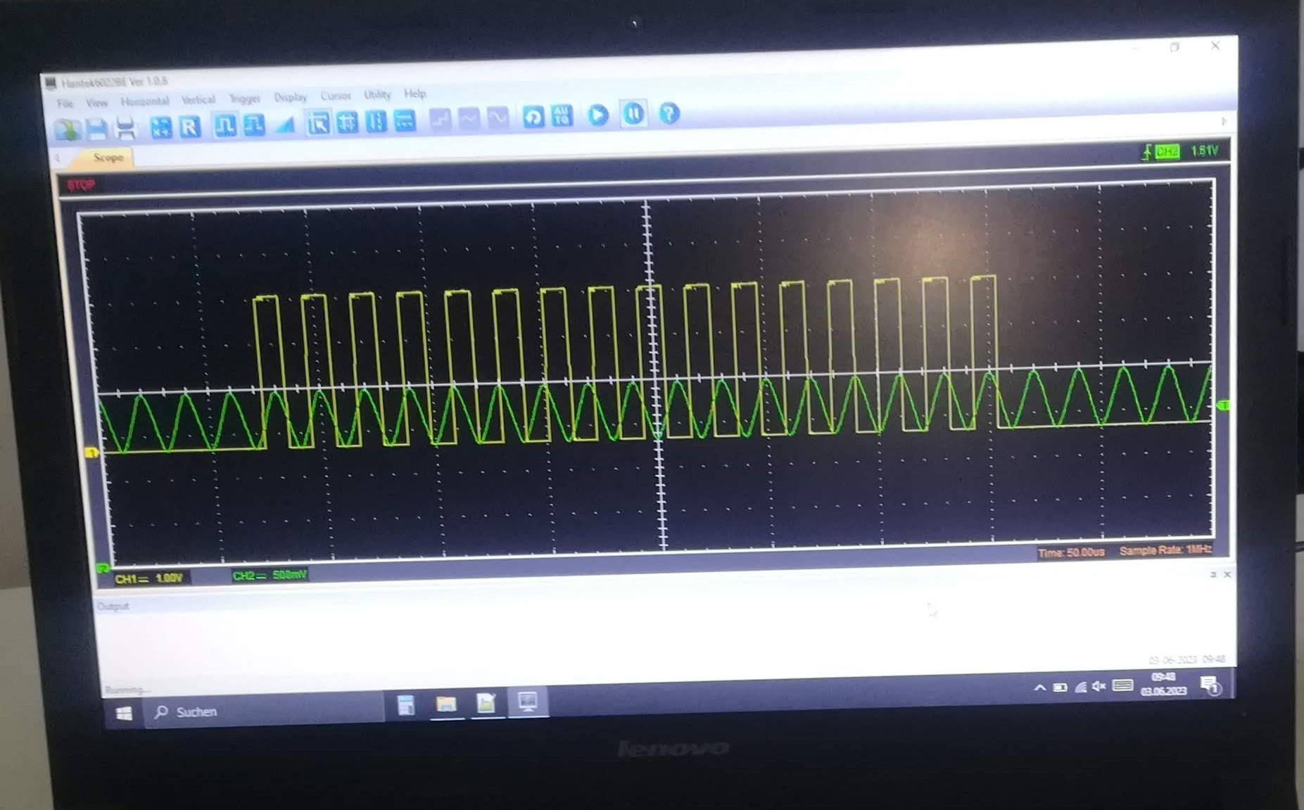
With the PIO feature, I generated the following 4 signals:
- Piezo Drive Signal 50kHz 20us
- Strobe LED Signal 50kHz 20us
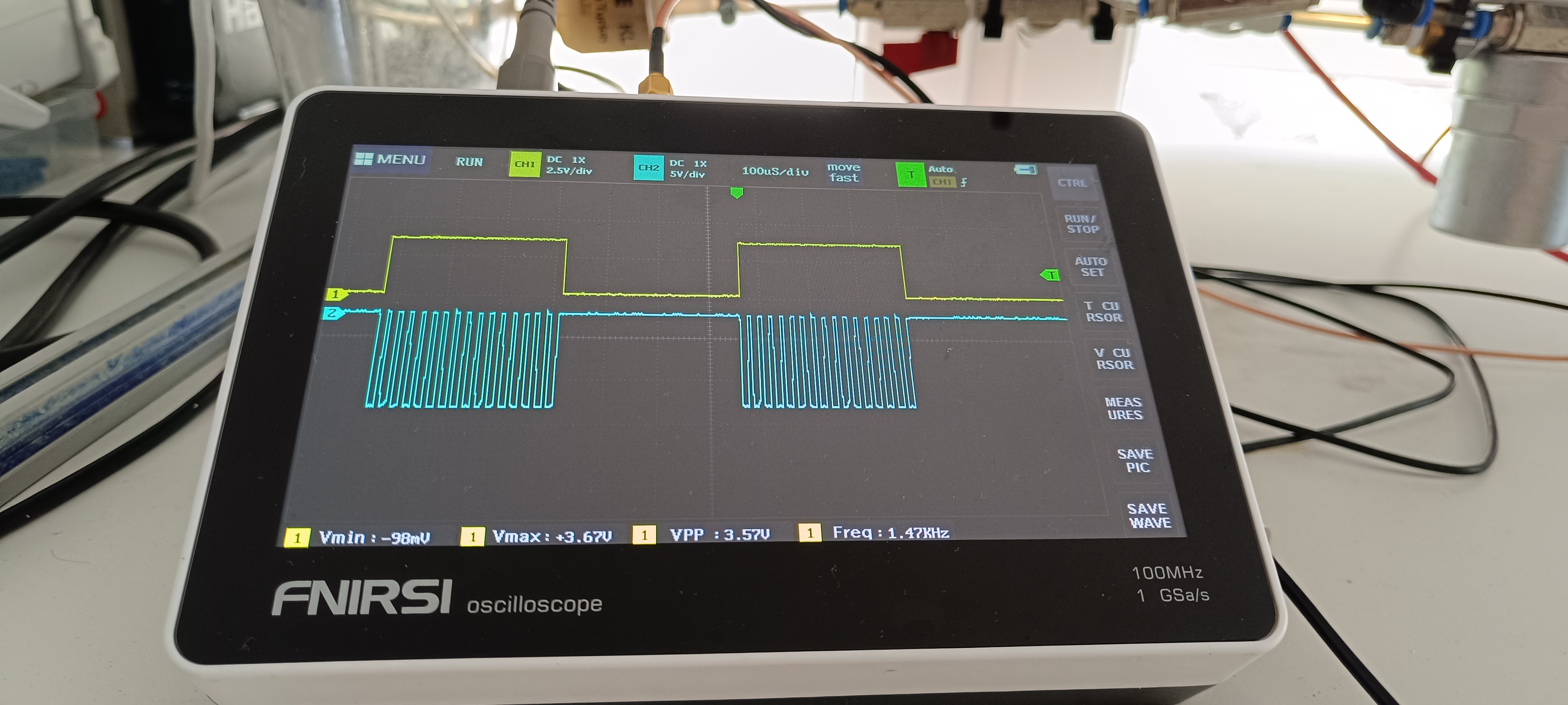
- Phase Detection Signal 1.47kHz 680us
- Oscilloscope Trigger Signal 1.47kHz 680us
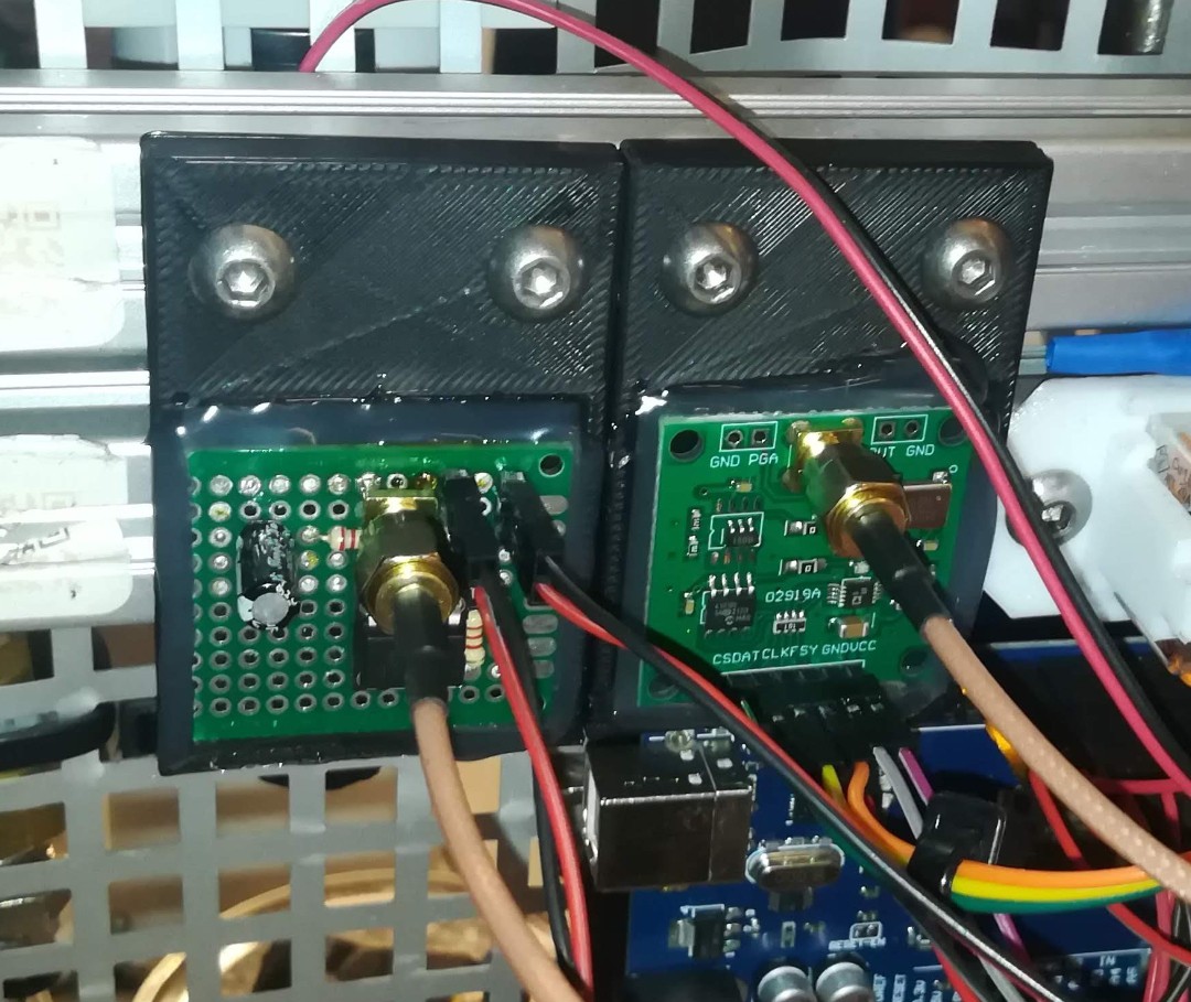
Because the output of the Raspberry Pi Pico is a digital signal with either around 0V or around 3.3V it was needed to filter the piezo drive signal with an RC filter to get a "close-to-sine-wave-shaped" signal.
At the current state of the project, the piezo signal gets fed into a 24V 100W audio amplifier, which amplifies it and sends it to the piezo ring at the nozzle.
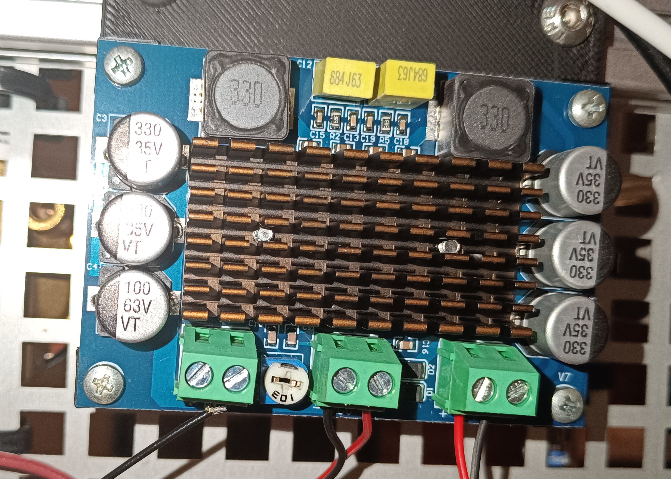
Maybe I will replace the audio amplifier with a dedicated piezo driver, later in the project to get a better drive signal. The square-to-sine wave RC filter is also not optimal and could later be replaced by something else.
Something like a circuit where you can feed in a 0V to 3.3V square wave and get a 100+V sine wave out would be perfect...Maybe later...
For the strobe LED I'm currently using a dedicated pin, which isn't really needed, because I could also just use the piezo signal. Both signals are the same when they exit the Raspberry Pi.
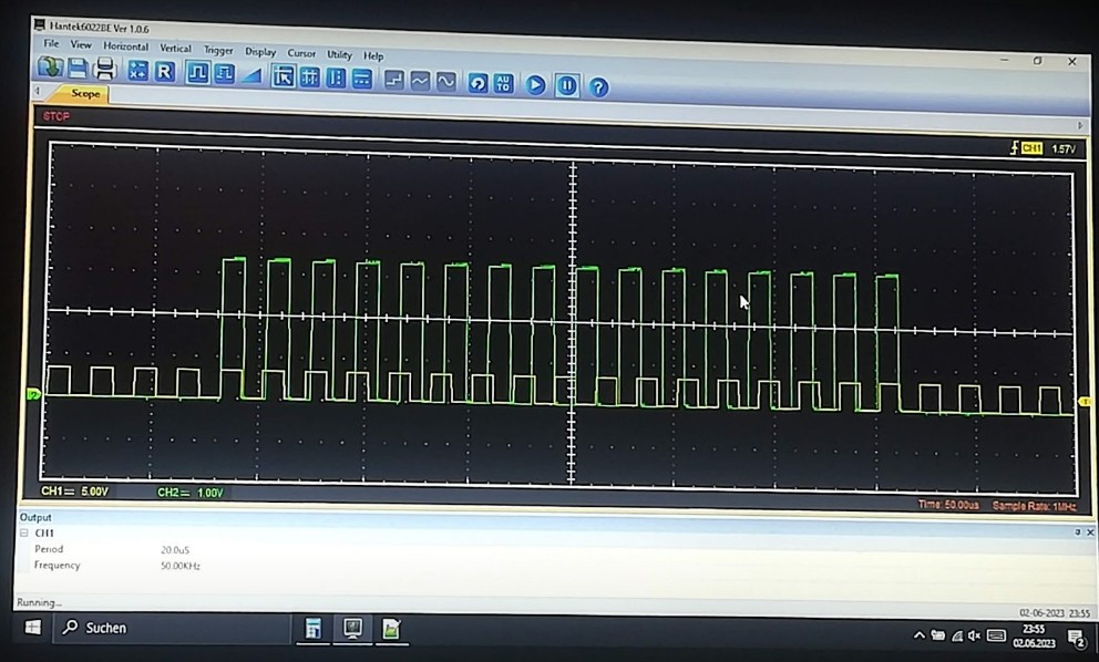
However, at the moment the output is not needed for something else and so it's possible to connect the strobe LED directly to the pin without additional wiring.
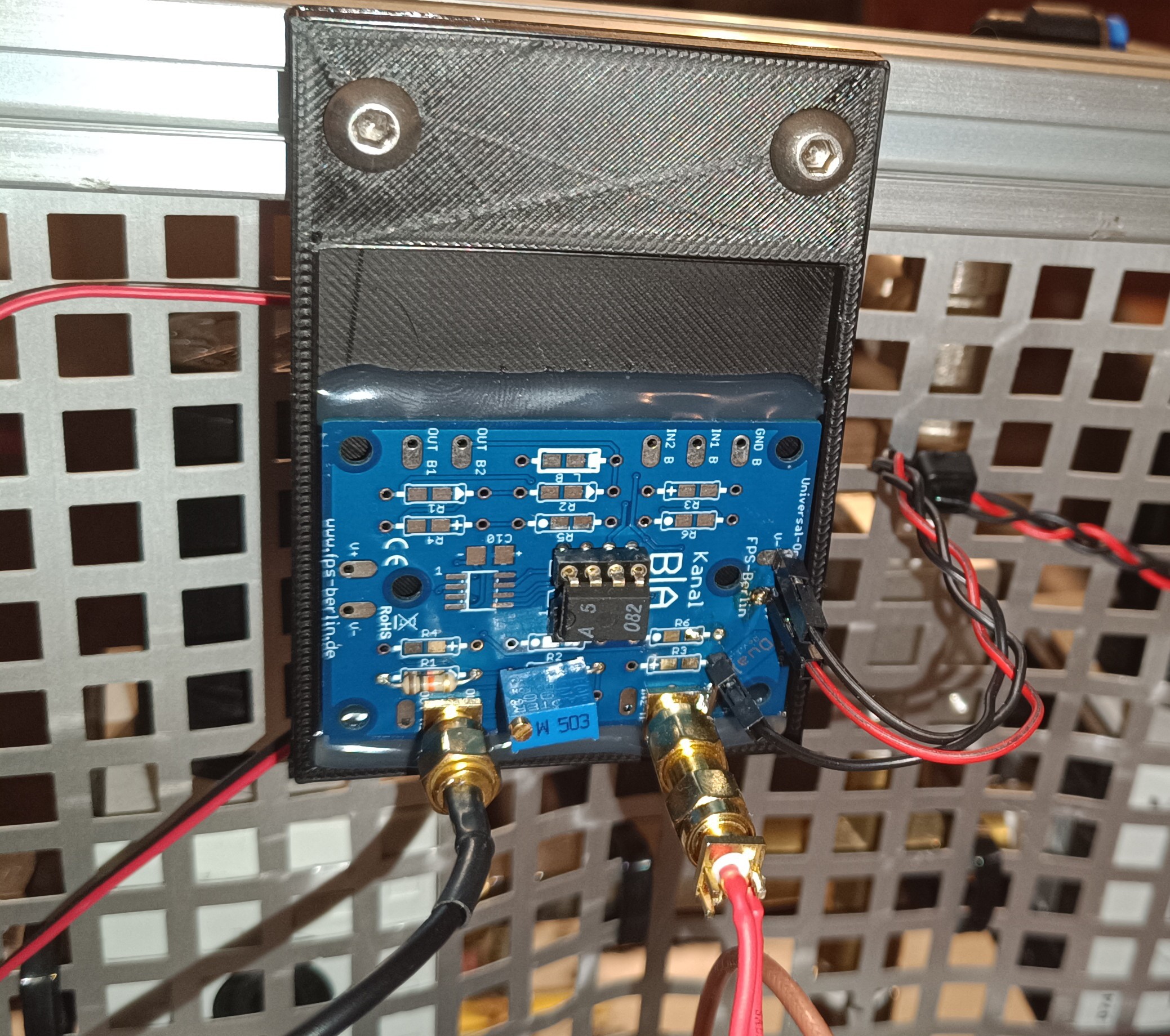
The phase detection signal is passed to an inverting amplifier circuit that amplifies and inverts it from 0V to 3.3V to around 0V to -12V.
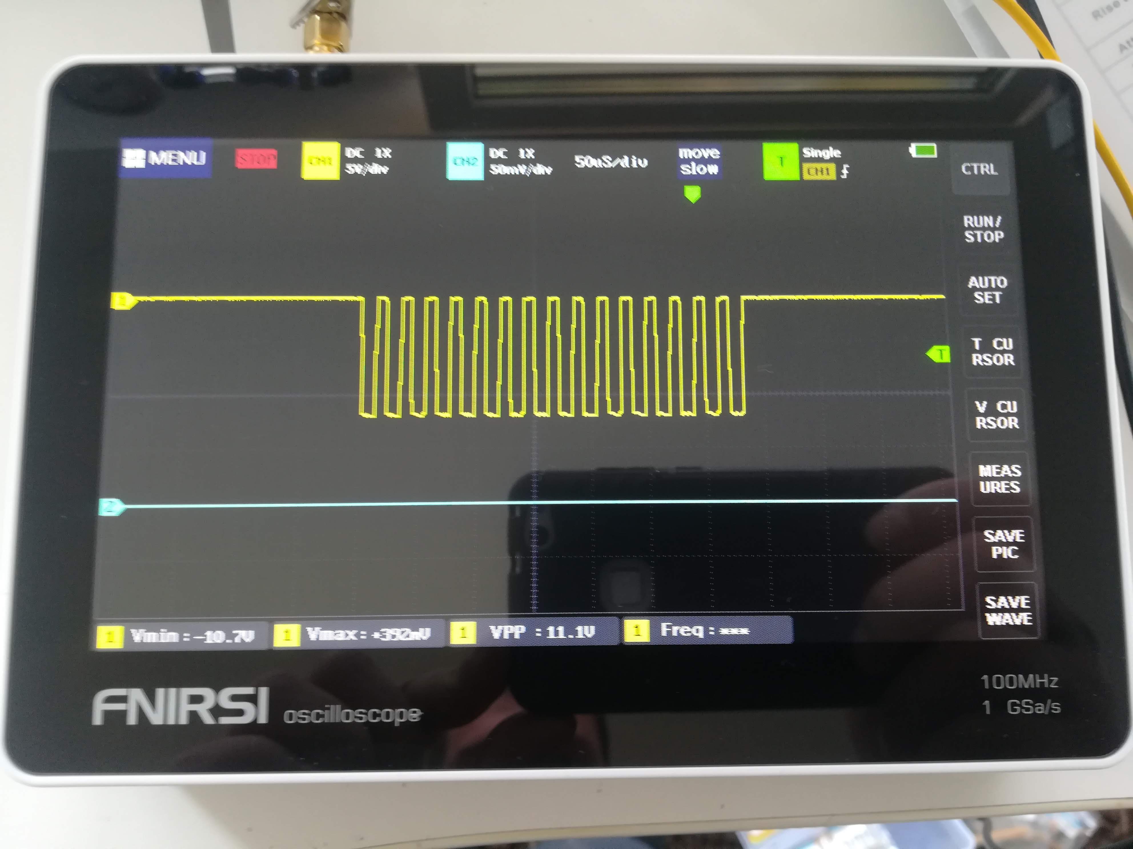
I added the trigger signal because my oscilloscope can not trigger the phase detection signal right - it keeps jumping back and forth.
The trigger signal is just a simple square wave with the same period as the phase detection signal of 680us, which is suitable for triggering the oscilloscope without any jumping.
At the moment I'm just using these 4 signals, which leaves me with another 4 PIOs for performing other tasks.
One will be needed for the feedback signal of the phase detection feature, about which I will write more in the next log and another one will be needed for the timing of the charging signal that charges droplets with a high voltage for printing.
I have no final plan, yet, for how the selection of the right voltage for print charging should work in the end. There are also other things that have to work first before I can start working on this.
But my idea at the moment is to send a timing pulse from the Raspberry Pi Pico's PIO output with the correct phase setting when it gets triggered from the main CPU.
It's not essential that the droplets which print a vertical line are droplets that form right after each other. It would be beneficial for printing speed, but it is more important to get it working at all, so if there would be "spaces" of uncharged droplets between charged droplets, it wouldn't be a problem, either.
So, the Pi has to get the vertical line pattern via serial from a PC or printer controller. Then it has to convert and send them for example via SPI or I2C to a digital potentiometer which controls the gain of an amplifier which controls the print charging voltage. Finally, it has to trigger the PIO which sends the trigger pulse to a transistor which then charges a single droplet.
If this process would take longer than 20us (better 15us, to have some margin) it would miss the opportunity to charge the following drop, which like I said before, wouldn't be a problem, either.
This was just a thought and the final solution for that could look completely different...
More about the Phase Detection Feedback Signal in the next Log.
Thanks for reading :)
Discussions
Become a Hackaday.io Member
Create an account to leave a comment. Already have an account? Log In.