 Dominik Meffert
I'm currently working on the feedback signal of the phase detection feature. This signal gets read from the ink droplets which get charged by the phase detection signal.
It took me multiple months until I was able to read anything from the ink droplets. My problem was that I couldn't find anything similar to the "reading of charge on small fast flying droplets".
I read in multiple papers that they used a lock-in amplifier for reading the droplet's charge, which is a pretty expensive instrument that can filter very small signals out of the surrounding ambient noise, by searching for it with the help of a reference signal with the same frequency.
Unfortunately, such an instrument would cost more than all other parts of the project and there also was no IC or ready-to-use module with similar capabilities (besides one from China with a long shipping time).
Another time where @Paulo Campos helped me by giving me the circuit of a CIJ printer's phase detection amplifier.
Thanks a lot, my friend :)
It turned out that the circuit only contained a TL072 Opamp as an amplifier and some filtering - so no lock-in amplifier was needed.
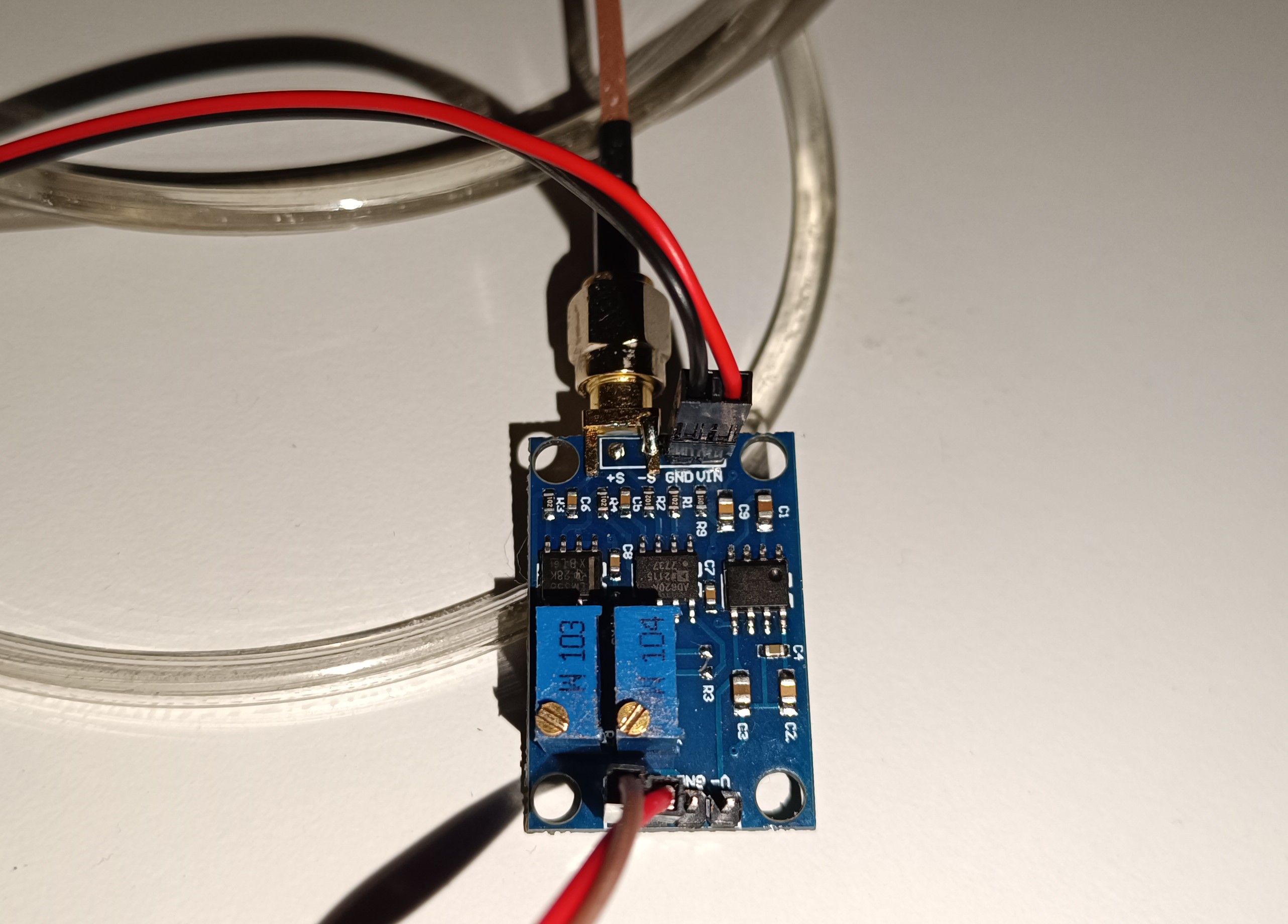
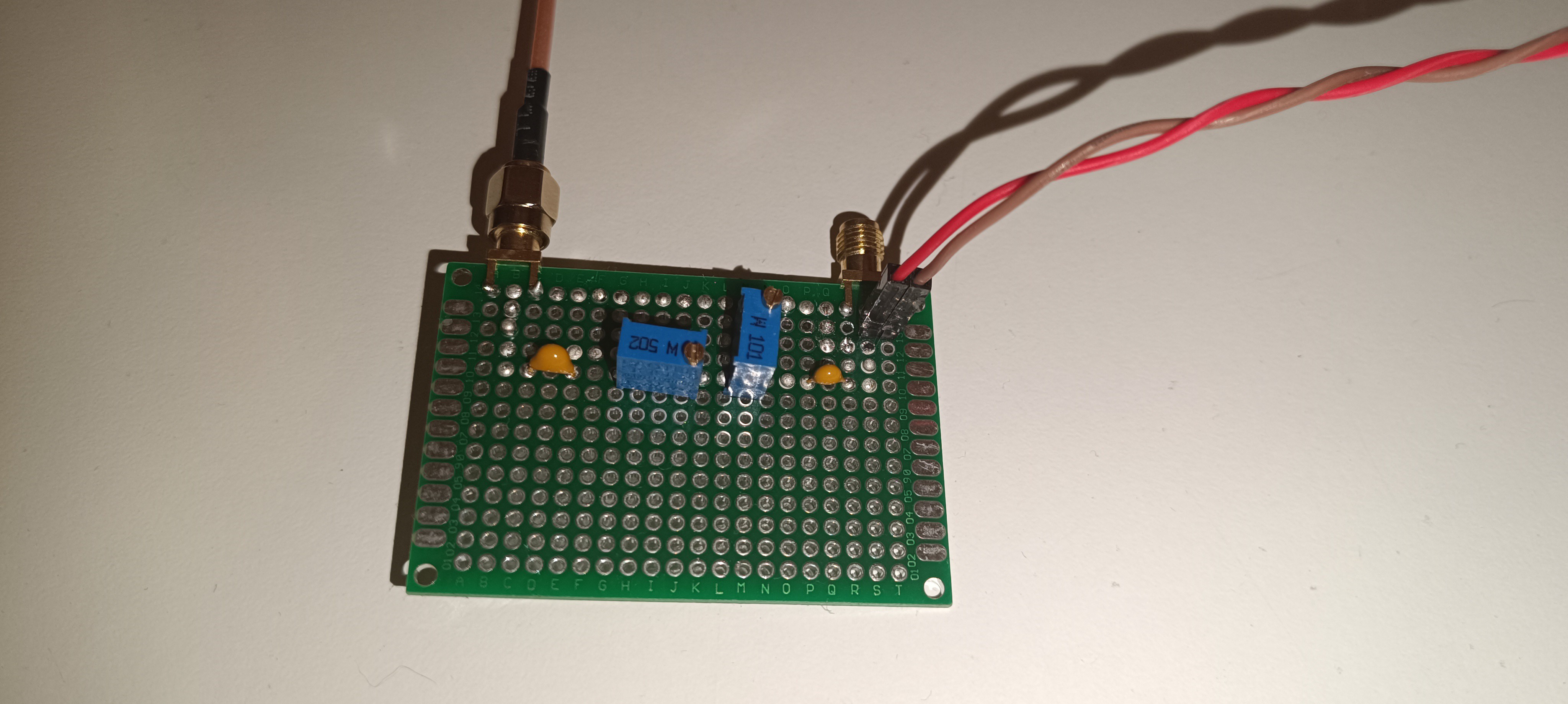
After building and testing the circuit 1:1 which didn't work with my DIY printer, I tried using an "AD620 small signal amplifier module" in combination with a self-built bandpass filter designed for 50kHz, which finally gave me a signal.
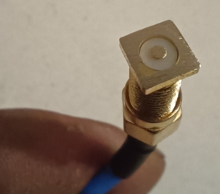
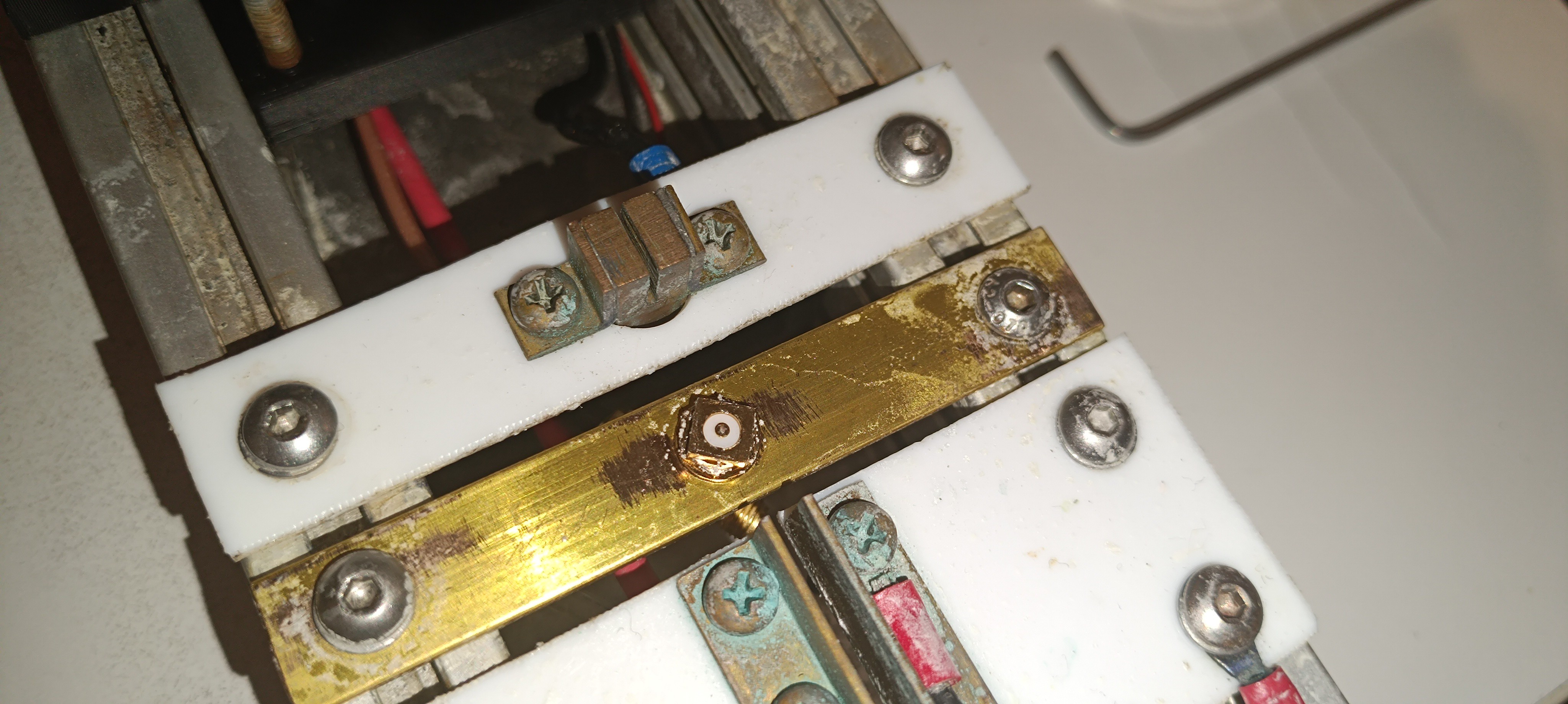
For the sensor or probe for reading the signal, I used a long SMA solder connector, from which I cut off and sanded down the legs to get a flat surface with the shielding on the outside and the probe pin in the middle. For the sensor, shielding is very important, because the signal that gets read from the droplets is smaller than the ambient noise and also smaller than the phase detection signal itself, which gets radiated out from the charge electrode.
Without good shielding, the sensor would pick up the signal from the charge electrode instead of the signal from the droplets.
With the new setup, I could finally get some signal that reacts to the presence of the ink droplets.
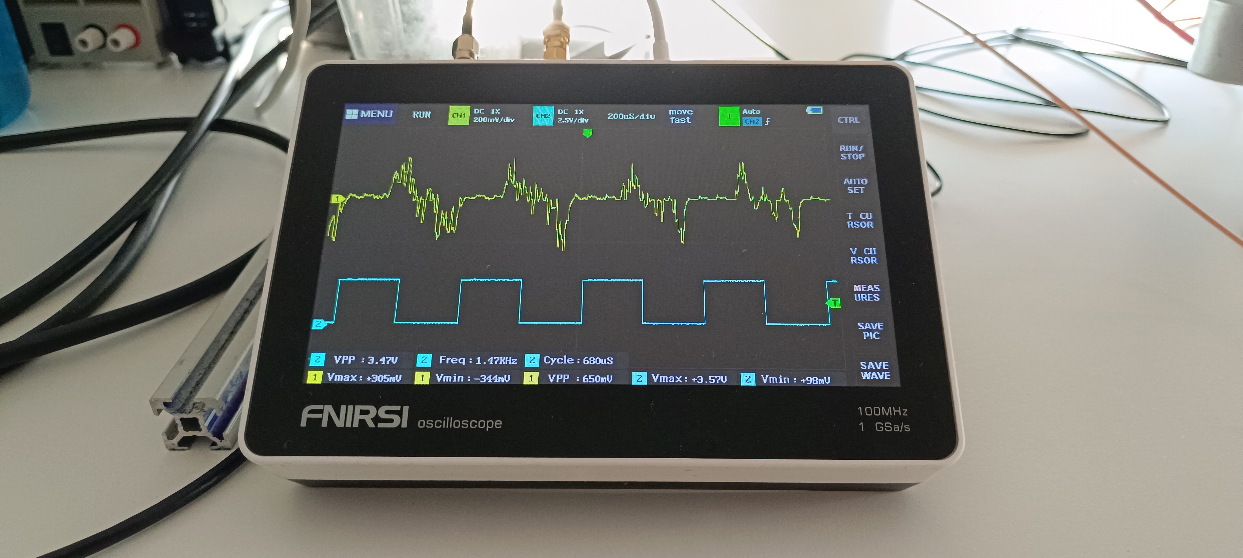
When I stopped the ink stream by blocking the nozzle with my finger, the signal disappeared and when I turned off the piezo, the signal got replaced by noise. The amplitude of the signal got decreased when the ink droplets passed the sensor at a higher distance and got increased when the ink droplets passed the sensor at a lower distance.
So, it should be the signal I'm looking for since November last year :)
But the signal is not perfect, yet. Normally the phase detection feedback signal has the shape of a hedgehog with the highest voltages in the middle and the lowest voltages on the outside. It shouldn't go negative either and it should also be more stable.
So, there will be some improvement needed until it can be used for selecting the right phase based on it.
However, having this signal gives me something to look at while adjusting things on the printer and doing improvements. I can change something and look at how it affects the signal which gives me a way of feedback that I never had before.
Here are some videos about ink stream detection testing based on the feedback signal:
It's nice to have something to show about this project, again.
Here is another test:
This time with 48V instead of 24V piezo drive voltage. In the video you can see that by adjusting the drive voltage the feedback signal also changes.
Thank you very much for your interest in my project :)
Discussions
Become a Hackaday.io Member
Create an account to leave a comment. Already have an account? Log In.