 Dominik Meffert
Great thanks to Robert and @Paulo Campos for helping me with this :)
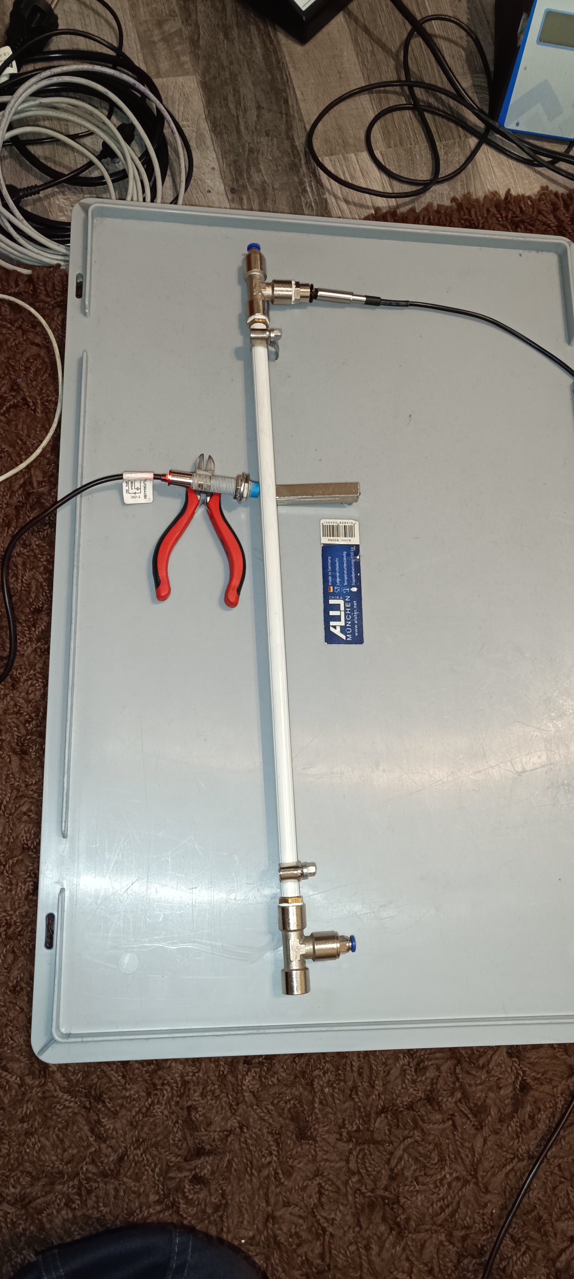
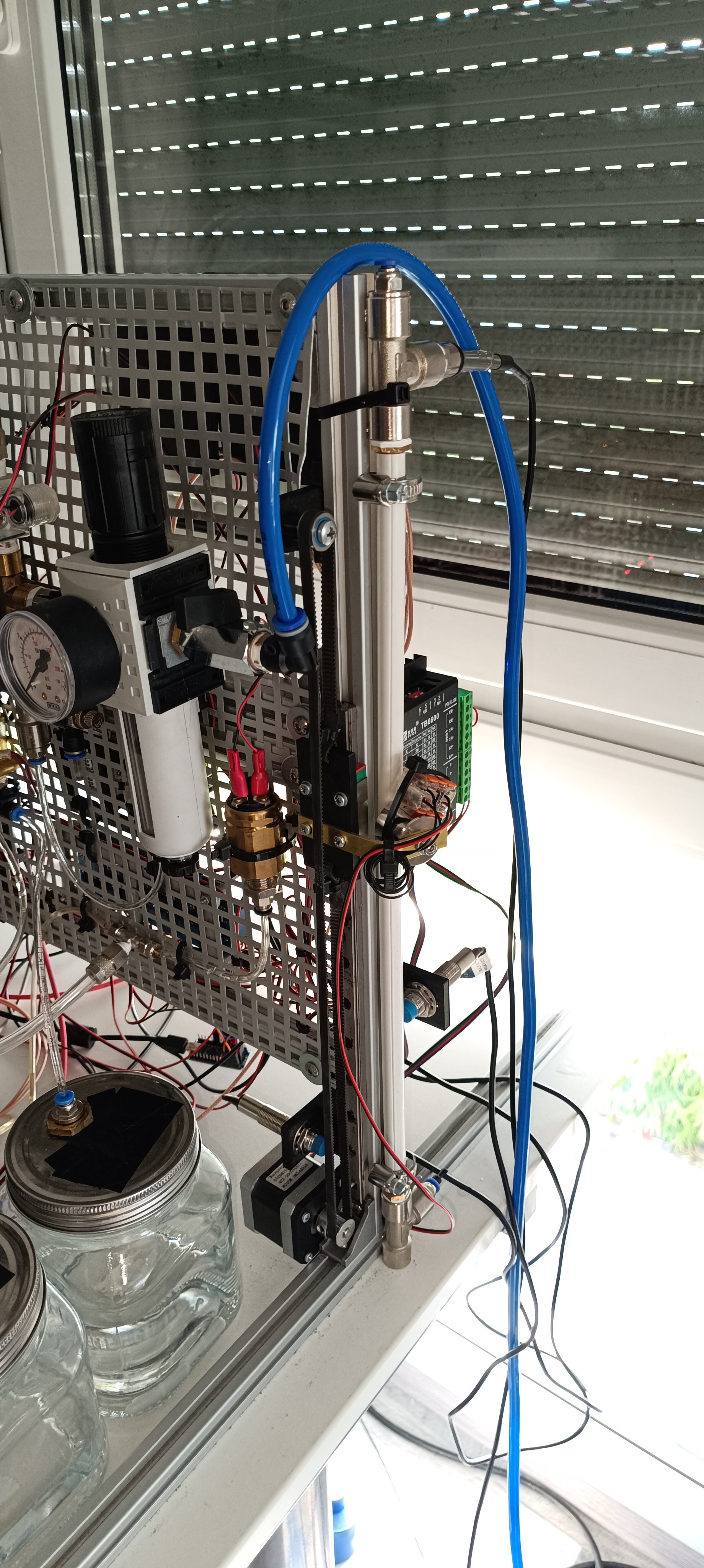
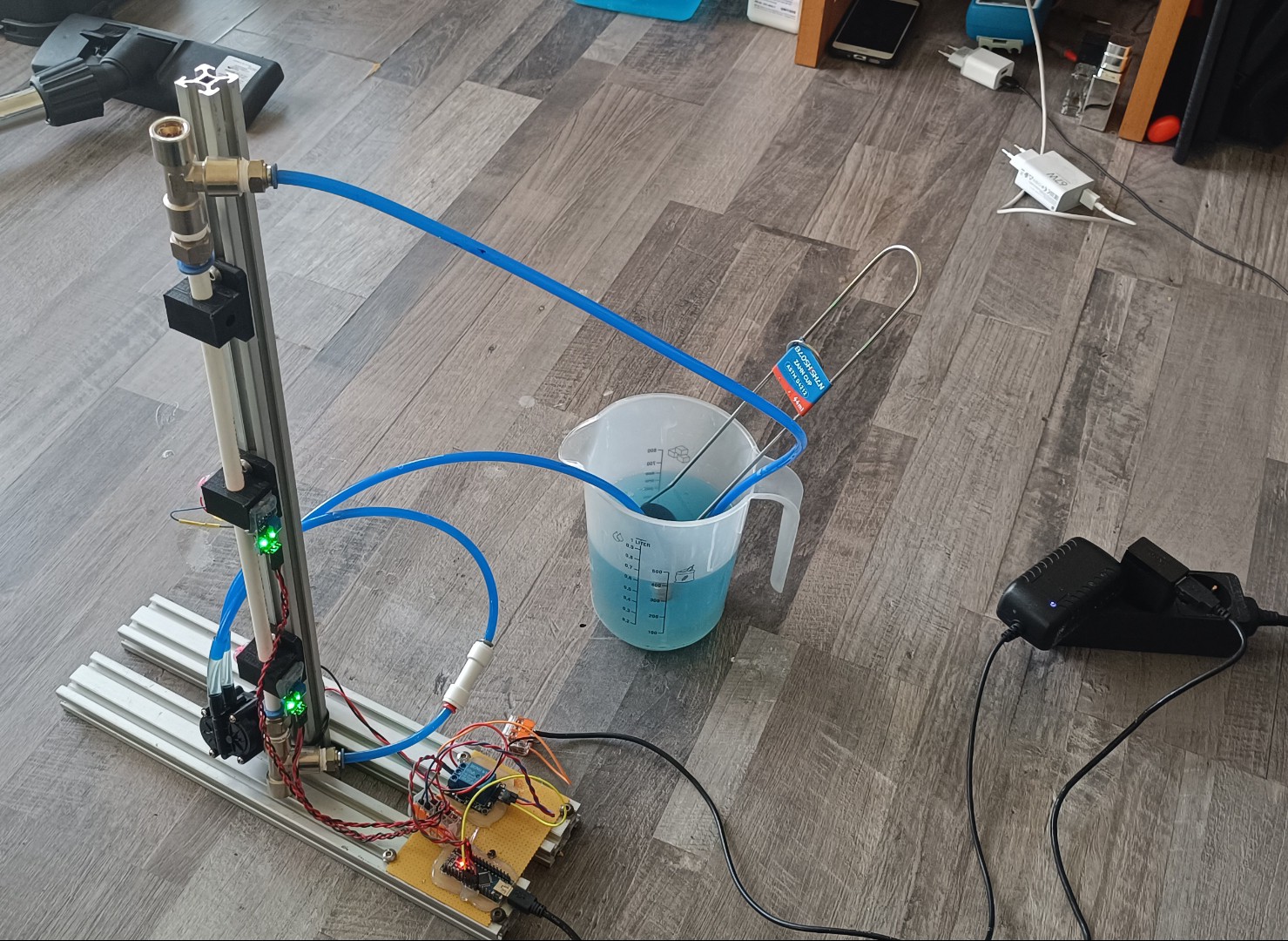
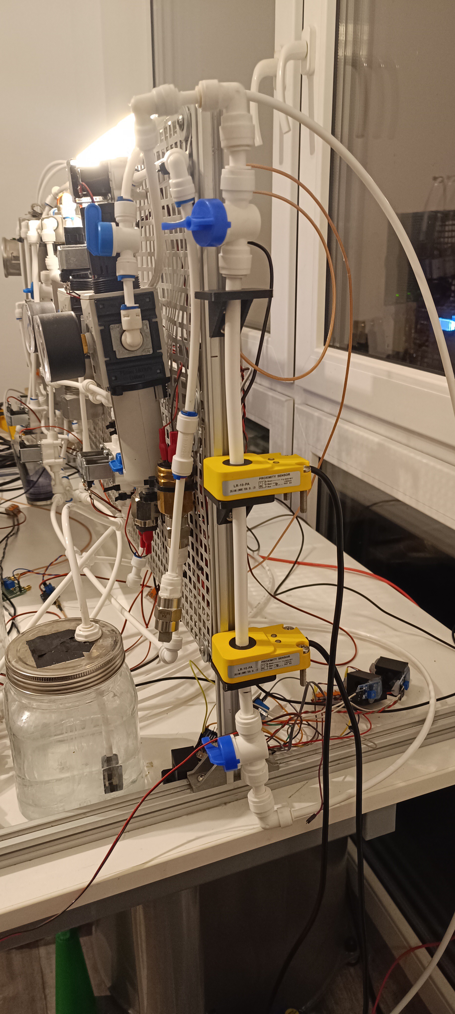
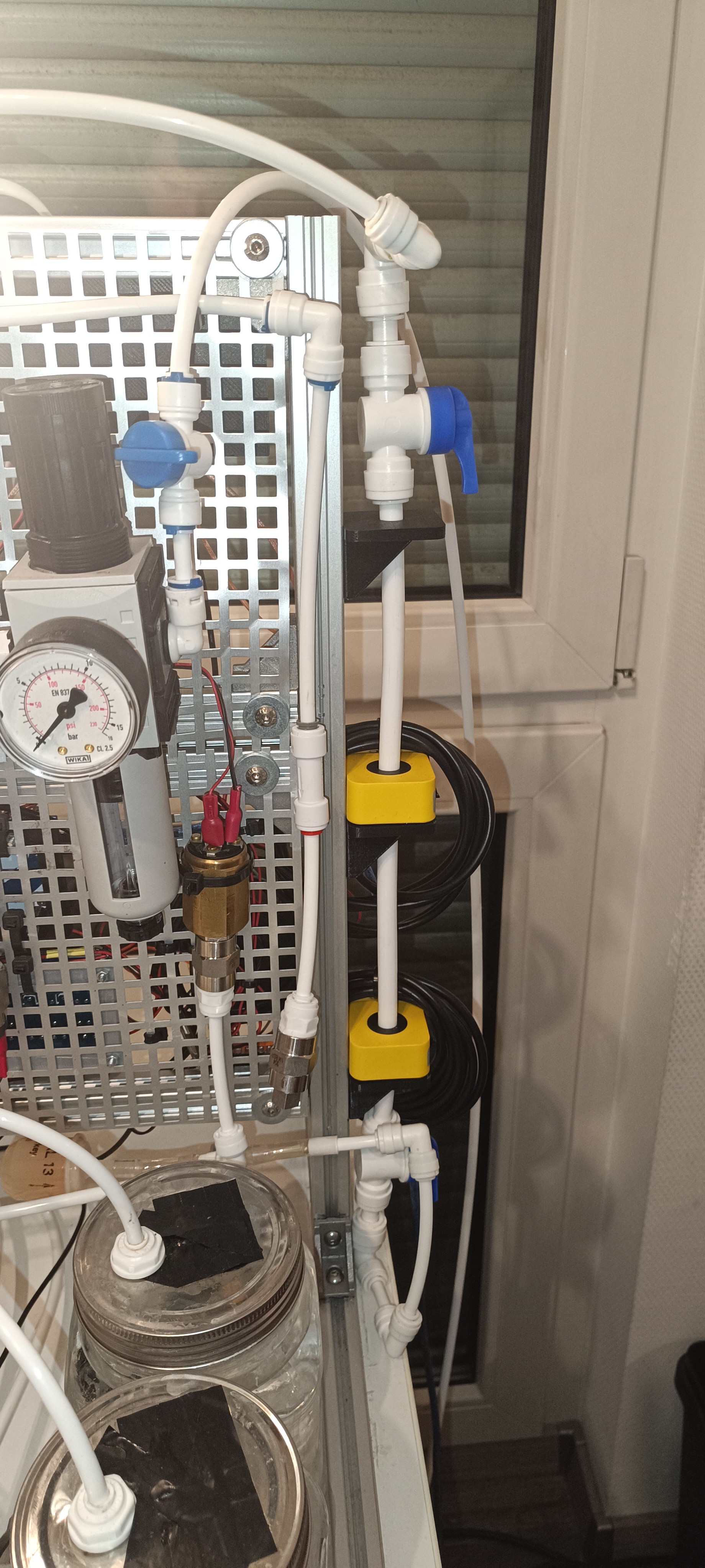
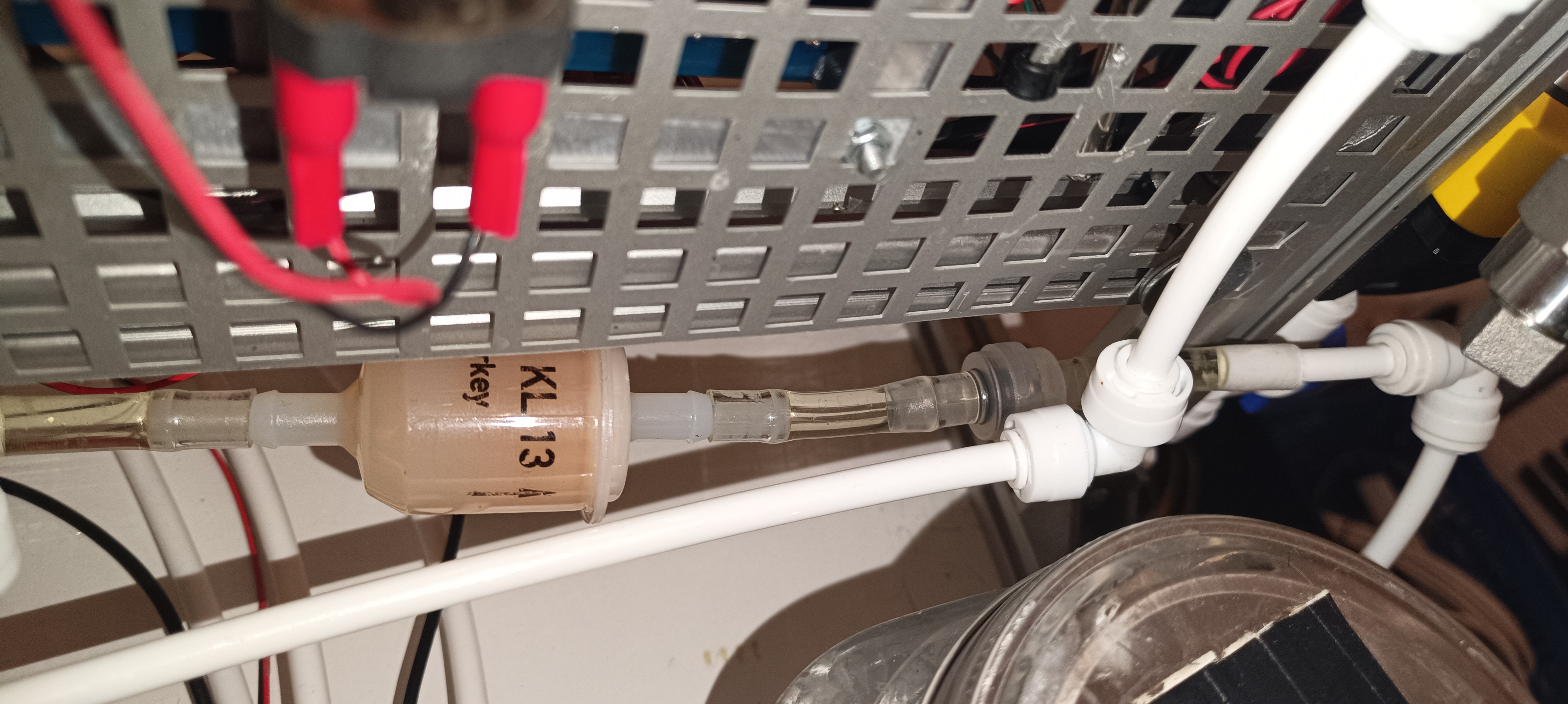
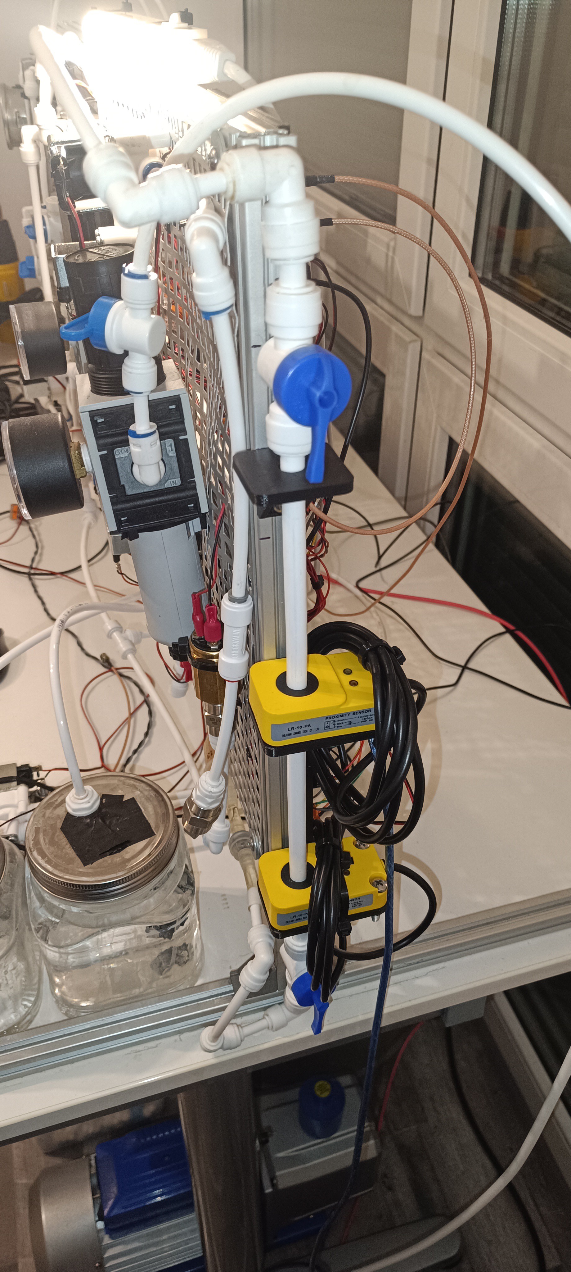
To measure the viscosity of the ink more reliably I replaced the drain time counter with a falling ball viscosimeter, another viscosity measuring method that is also used by many commercial CIJ printers.
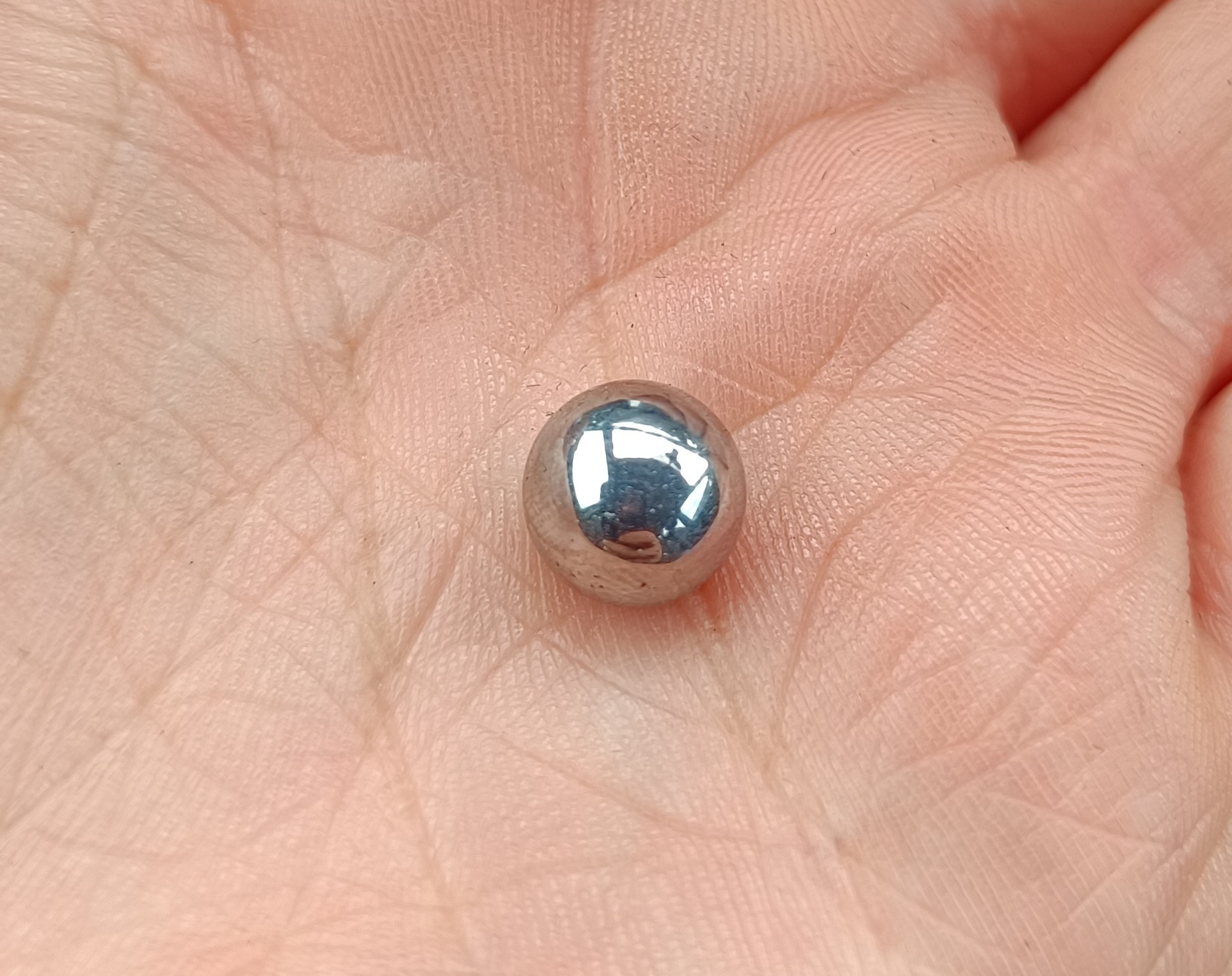
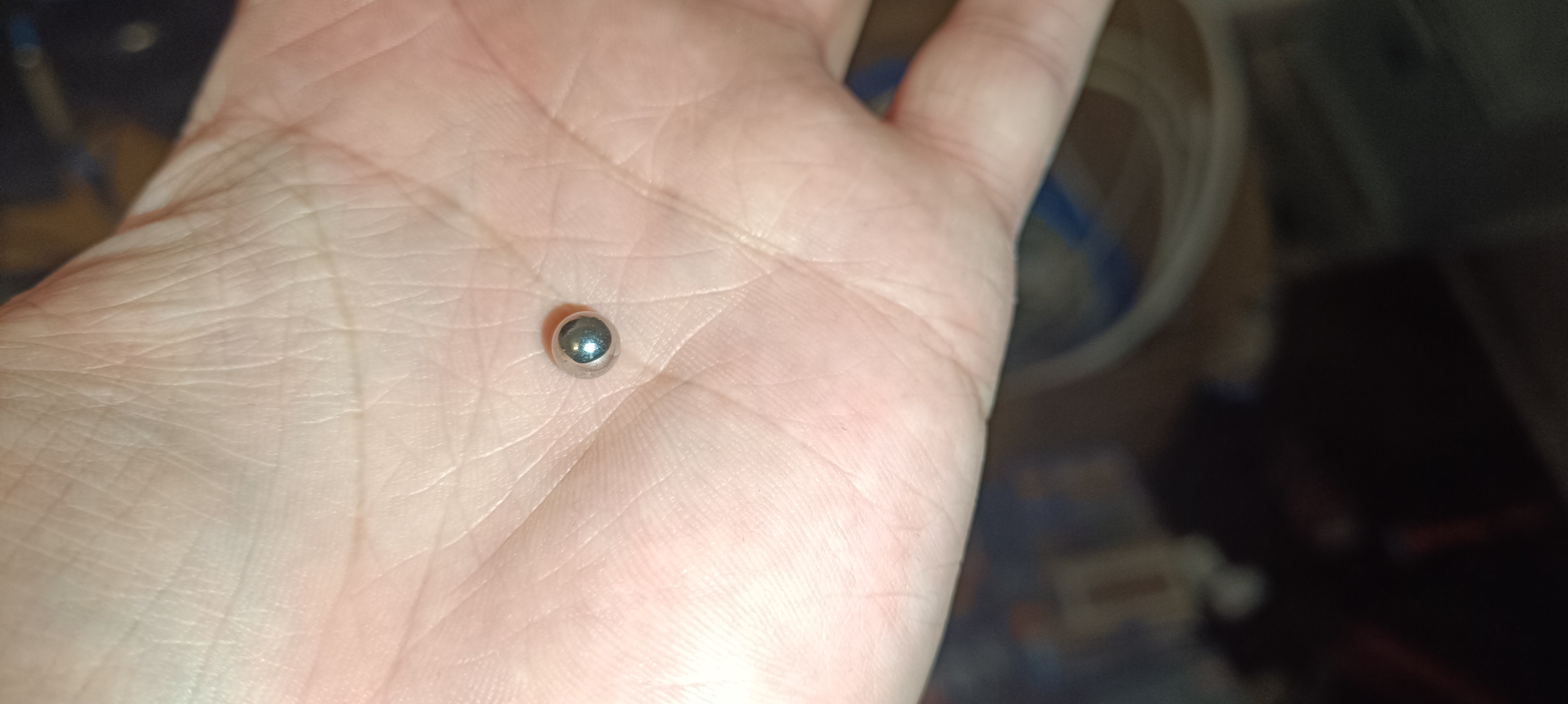
The falling ball viscosimeter works by counting the time a (steel) ball takes to fall a certain distance inside a tube that is filled with the fluid of which the viscosity should be measured.
The size and weight of the ball and the distance never change, but the time reading will change with viscosity. The fall time increases when the viscosity gets higher and decreases when the viscosity gets lower.
I did a lot of testing with it and as long as the fluid inside the tube doesn't move, the time readings are quite stable.
Here is my progress on it in chronological order:
First test of the Viscosimeter
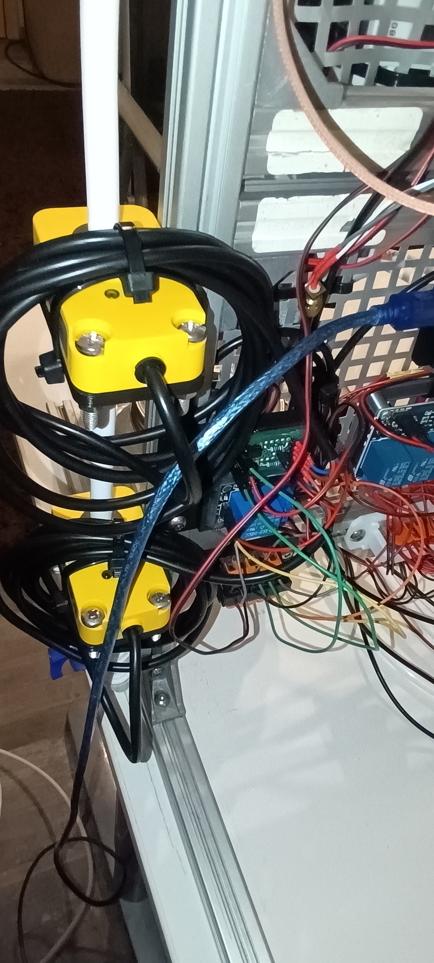
Test of the Stepper Motor Lifter
Test of the Pump Lifter
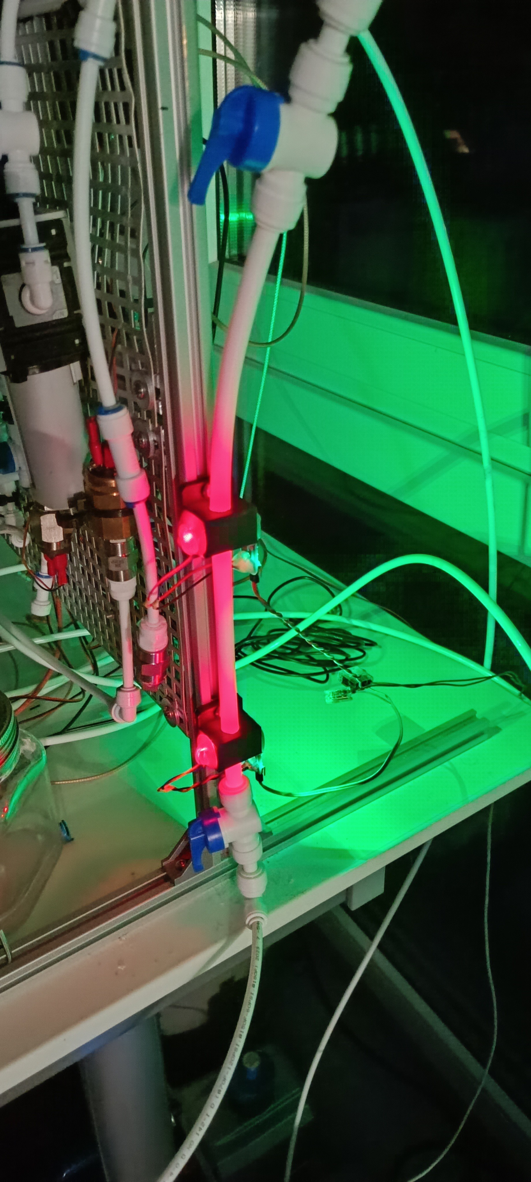
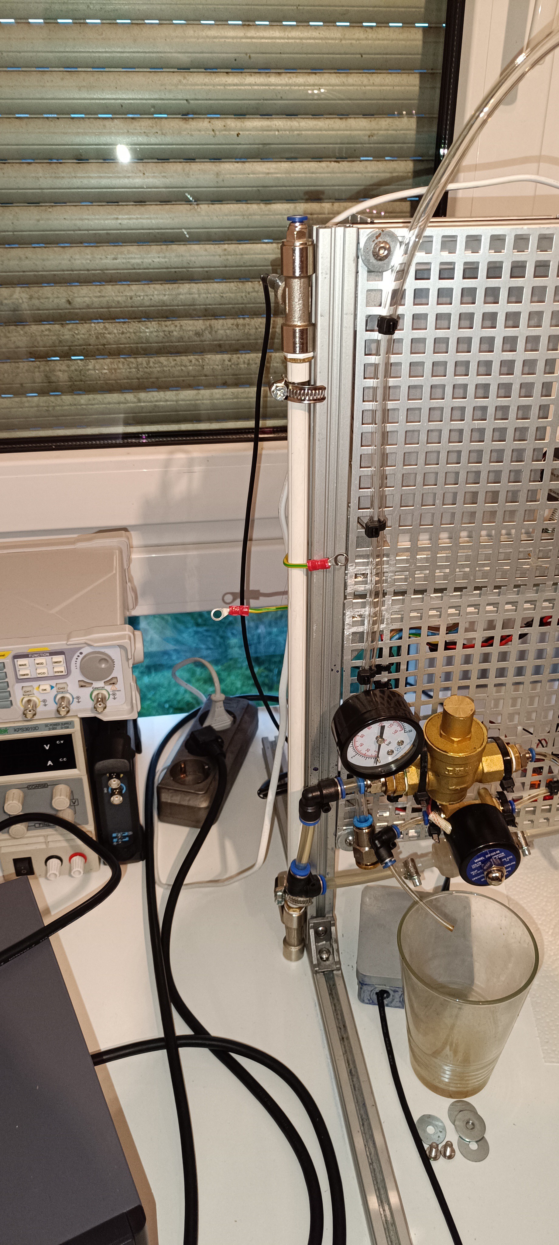
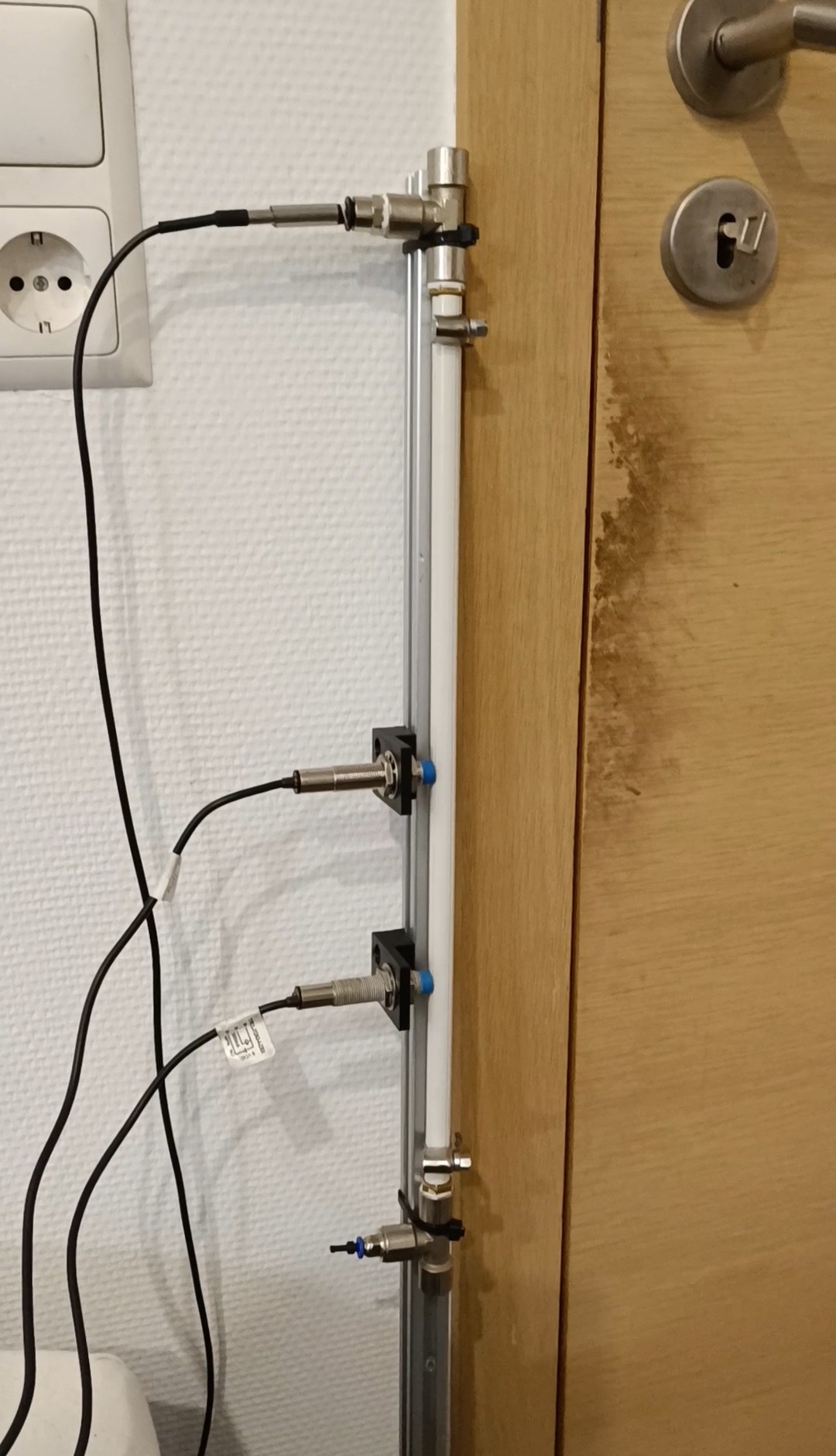
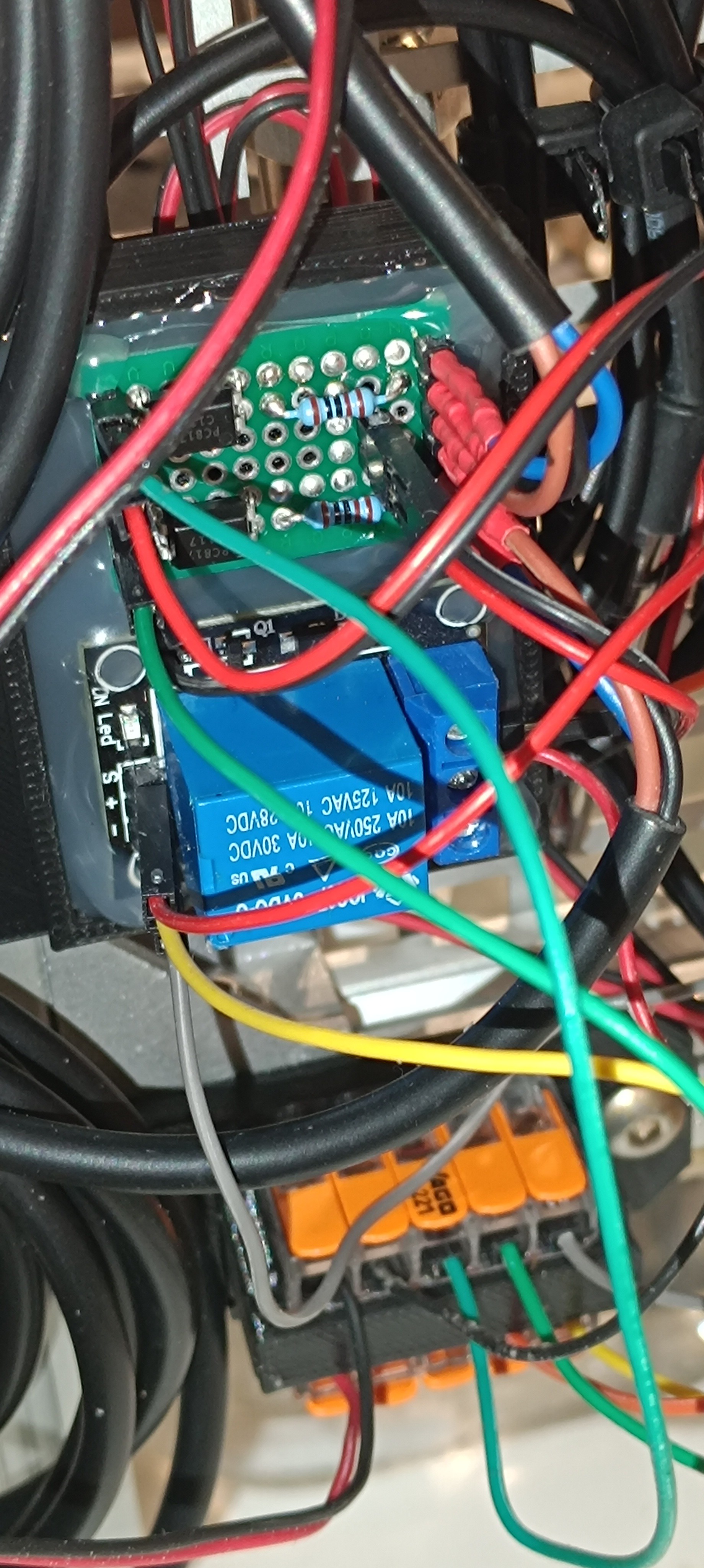
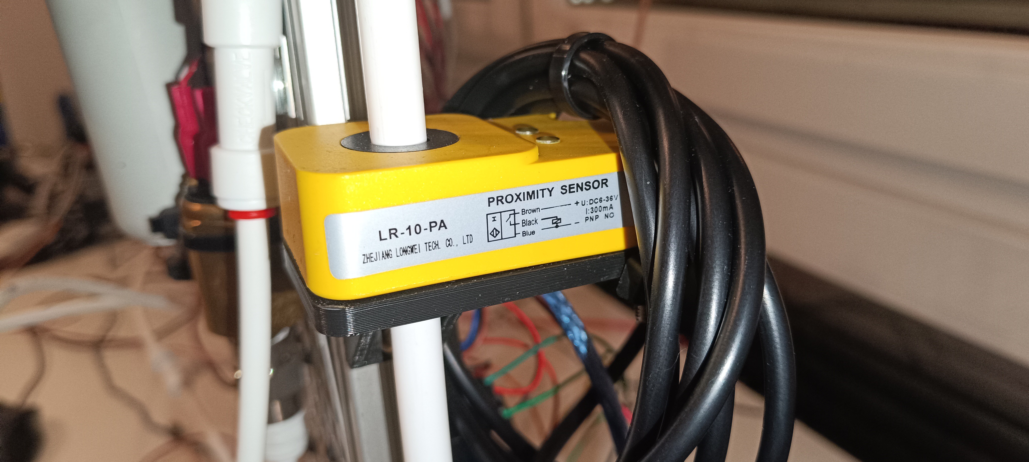
Test of the optical Sensors and Pump
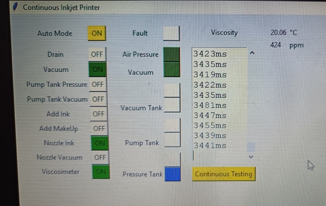
Continuous Testing - No Pause between Readings
In commercial CIJ printers, the viscosimeter is calibrated by selecting the ink type that is used and doing some test readings with it. Based on the test readings the printers can calculate the relation between measured time and viscosity. This is possible because the exact viscosity of the used commercial ink type is known and always the same. Over time, some of the solvent in the ink bottle can evaporate which increases viscosity, so it's recommended to always use a fresh ink bottle for calibration. With the right calibration, the printers can show the actual kinematic viscosity reading in cPs.
In theory, it would be possible to use this method for this DIY CIJ printer - ordering some ethanol based CIJ printer ink and using it for calibrating the viscosimeter. The problem with it, besides the high price of CIJ printer ink, is that the ink's viscosity is not shared with the public so there would be no reliable values for calculation. It's stated that the ink's viscosity is usually around 5 cPs, but for calculating a precise conversation value it would be no bad idea to get the exact viscosity from the ink's manufacturer. With some luck, it could still be possible to find one ink that has a datasheet that mentions its viscosity. In this case, this ink could easily be used for calibrating the viscosimeter and also for printing if the price tag doesn't make it unattractive compared to self mixed ink.
Another way would be buying some calibration oil (oil with known viscosity) which probably could provide reliable values for calculation. The problem with it would be that for the calibration all lines would have to be cleaned from ink, then filled with oil for calibration, then cleaned again, and then filled with ink again to prevent mixing of both fluids and contamination of the ink. So, with some effort, this could also be a way to get readings in cPs from the viscosimeter.
If no ink or oil is used for calibration it should also be possible to find out the optimal viscosity by keeping the ink pressure steady and looking at the feedback signal while increasing and decreasing the viscosity. The breakup and charging should be the best at the optimal viscosity and should get worse when it's too high or too low. This way it should be possible to only use the time reading of the viscosimeter without calibration.
My personal guess would be that the time count will be enough to keep the printer working.
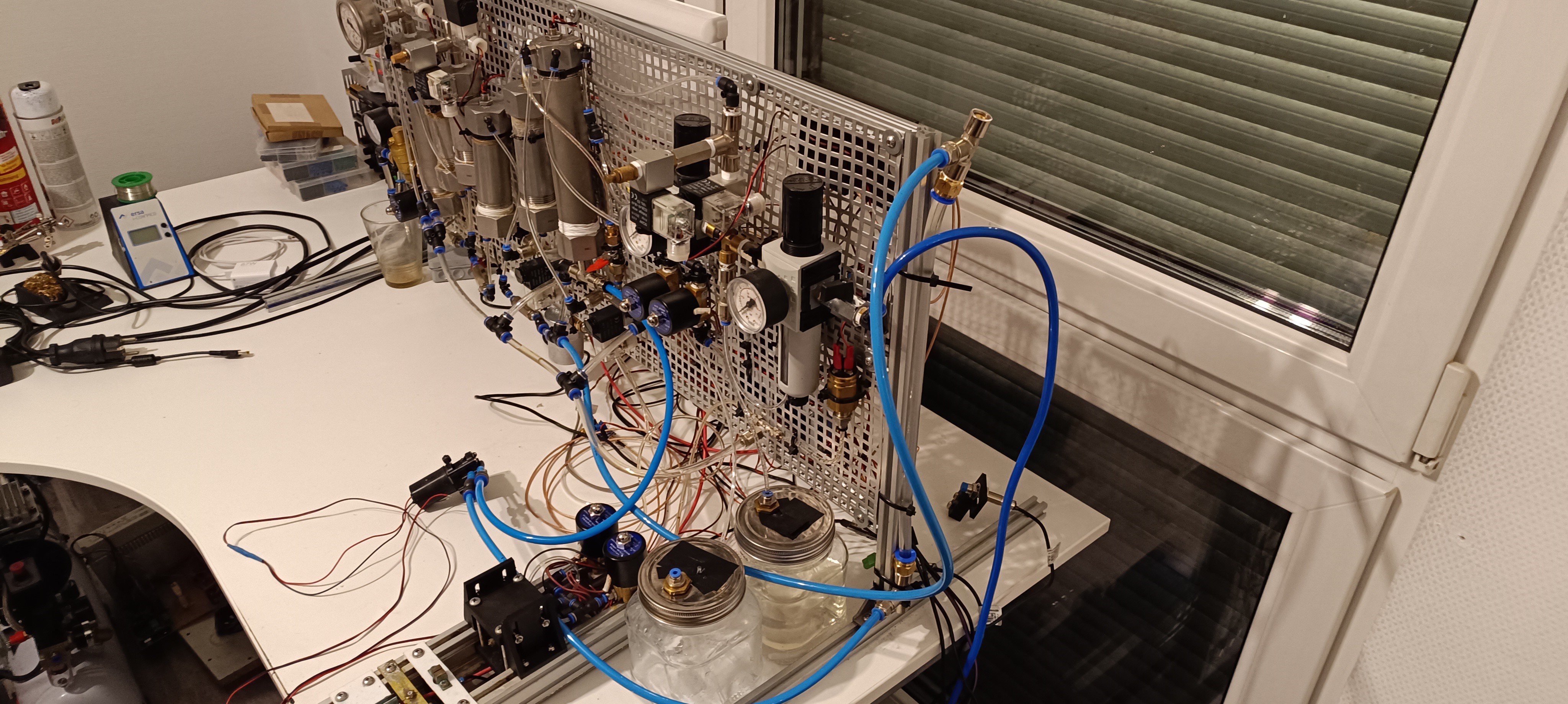
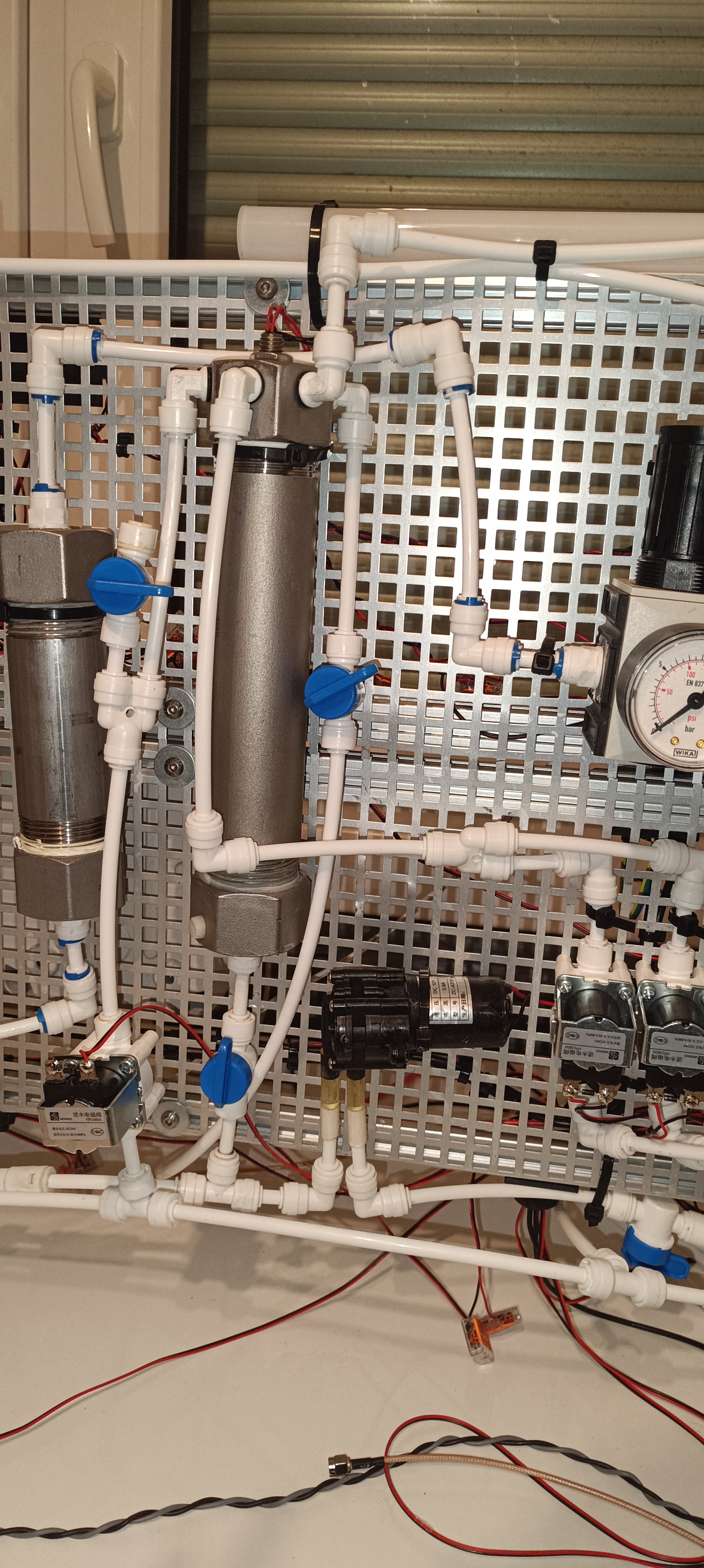
I'm currently working on the feedback signal analysis and also looking if I can replace the pneumatic based setup with a pump based setup to reduce the complexity of the printer.
Great thanks for your interest in my Project :)
Discussions
Become a Hackaday.io Member
Create an account to leave a comment. Already have an account? Log In.