Background
My wife and I race and cruise our 1987 J/35 sailboat on Lake Erie . The J/35 is an amazing boat and a very competitive racer that can still be day-sailed and cruised with just two people. We love our boat.

Soon after we bought our boat in 1995, we bought a Silva Nexus "Classic" instrument system which is now 25 years old. The Nexus system has performed well for us and it has held up well, too. The system consists of the Nexus server, three LCD displays, and four sensors: a paddle wheel boat speed transducer, an ultrasonic depth transducer, a gimballed fluxgate compass, and a wind instrument. The Nexus server also receives input from a Garmin GPSMAP 76CSx for position and waypoint information.
The Problem
The Nexus system has performed well for all of these years; however, the LCD instrument displays have lost their contrast and have become very difficult to read. Figure 2 shows the displays with an e-paper display taped over the middle display to demonstrate the difference in contrast. I could attempt to replace the transflective LCDs but I've also been frustrated by the limitations of the Nexus server - the Nexus data bus is proprietary and I'd like more control over instrument calibration and what data get displayed. Someday I will replace the whole aged system but in the meantime I'm dabbling with my own concepts to replace the server and displays while retaining the sensors.

Overview of the Solution
To reverse engineer how the sensors work, I've piggy-backed an Arduino-based data logging system onto the Nexus server to record the sensor values. The Arduino also reads and logs the data from the Nexus server and from the Garmin GPS at the same time. All of the data are formatted in NMEA-style strings that are sent from the Arduino to an Android tablet using an HM10 BLE transceiver. The Android tablet is running an MIT App Inventor app that receives, parses, and logs the BLE data to a file on the SD card for later analysis. My purpose for collecting the data from all three sources (raw sensor data, Nexus data, and GPS data) is to allow me to correlate the responses collected by the different methods, to improve on the calibrations, and to devise my own responses.
The current state of the project is still experimental. I have my Arduino hardware cobbled together and temporarily wired to the Nexus server using a scavenged, chopped-in-half VGA cable so that I can remove the Arduino to work on it in a more comfortable and convenient location than the bowels of the boat.
All of the Nexus sensors produce analog signals with pulse widths proportional to boat performance responses. These sensors are archaic compared to modern smart sensors that collect and process their own data and put the processed data on a NMEA or a proprietary data bus.
Hardware
Silva Nexus Server
The Nexus server (Figure 3) is the brain of the instrument system. It is powered from the boat's 12VDC system, reads and processes sensor data and data from the GPS, and outputs data to three two-line instrument displays that are mounted up on deck. The server has an RS232 serial input port to receive data from external devices like a GPS and an RS422 serial output port for communication with a computer.

Boat Speed Transducer
The boat speed transducer is the simplest of the Nexus system's sensors. The transducer, show in Figure 4, consists of a plug that fits into a thru-hull fitting. At the end of the plug is a recess in which a paddle wheel is mounted on a stainless steel pin/axle. The paddle wheel has four blades. Two opposing blades contain small magnets, one with the north pole facing outward and the other with the south pole facing outward.

As the paddle wheel spins, the magnets pass by a bipolar Hall effect switch embedded in the plug face. The Hall effect switch output toggles between 0 and 5VDC with each passing of a magnet producing a 50% duty cycle square wave signal. The Nexus server measures the period of the square wave which is inversely proportional to the boat speed according to:
Boat Speed = 0.278 / Period
where boat speed is in knots and the period is in seconds. The constant 0.278 is Nexus's recommended calibration factor.
The boat speed transducer's square wave output is fed to one of the Arduino's hardware interrupt pins and the time between CHANGE events (T) is measured in interrupt service routine (ISR) code. The CHANGE event fires twice per cycle so Period = 2T and
Boat Speed = 0.139 / T
where the time between change events is in seconds.
Depth Transducer
The depth transducer system consists of three components: a 185 kHz piezoelectric depth transducer, the transducer amplifier/driver, and the Nexus server. The transducer and amplifier are shown in Figure 5 and a block diagram of the components is shown in Figure 6.

The piezoelectric transducer is mounted in a thru-hull fitting in the hull and the amplifier is wired between the transducer and the Nexus server. The cable between the amplifier and the transducer delivers the power pulse from the amplifier to the transducer during an output ping and returns the echo when it is received. There are four wires that pass between the server and the amplifier: 12VDC power, ground (both power and signal), and two signal lines that carry the ping and echo trigger signals.
During a depth measurement cycle a ping trigger signal is sent from the server to the amplifier. This signal line rides high at 8VDC (open collector in the amp) and gets pulled down to 0V for 500us to trigger a ping from the amp. Upon receiving a ping request, the amp applies the power pulse to the transducer, goes into a short quiescent period while left-over noise from the ping subsides, and then listens for the echo. When the amplifier receives the echo, it pulls the echo signal line down from 5VDC (open collector in the server) to 0VDC for 500us. The Nexus server measures the time delay between the ping and echo pulses. The speed of sound in water is about 4850 ft/s so the water depth is given by:
Depth = 4850 x Time Delay / 2
The division by 2 is required because the distance the sound pulse has to travel is twice the depth (down and back).

The ping and echo signals passing between the Nexus server and depth amplifier could be sent to two hardware interrupts on the Arduino; however, to conserve a hardware interrupt pin on the Arduino I made an SR latch from two NAND gates of a SN74LS00 quad 2-input NAND gate chip to combine the ping and echo signals into a single output signal. The circuit is shown in Figure 7. The output of the SR latch goes from low (0V) to high (5V) on the ping event and from high to low when the echo is received. A blocking 1N4148 signal diode and 5V pull-up 10K resistor protect the Arduino's input from the 8VDC of the ping signal line.

Compass/Heading Sensor
The Nexus server supports a magnetic compass/heading sensor. I have a gimballed fluxgate compass, shown in Figure 8, that came with my system but it is very old technology and has substantial errors that I was never able to calibrate out.

There are several generations of newer heading sensors but I've never used one. Luckily Lake Erie doesn't have any substantial currents so I have the Nexus server configured to use the GPS track heading instead of the compass sensor's heading. This is not ideal. We do sometimes sail in current and there are leeway (side-slip) effects that cause the boat's heading and track to diverge, which affects calculated responses like true wind speed and true wind direction. Eventually I would like to add an electronic compass/heading sensor to the system but I have not found anything that I'm happy with yet. I would like to try Kris Winer's USFS Max sensor (https://www.tindie.com/products/onehorse/usfsmax-module-and-carrier/, https://hackaday.io/project/160283-max32660-motion-co-processor/log/186576-new-product-brief) but I haven't had time to obtain and evaluate one yet.
Wind Instrument
The Nexus wind instrument is an amazing piece of art and engineering. I haven't seen another wind instrument like it. Other marine wind instruments have two independent transducers - an anemometer for measuring wind speed and a wind vane for measuring wind direction. The Nexus instrument integrates those two pieces of hardware into one elegant unit. Figure 9 shows the Nexus NX2 second generation unit consisting of a streamlined head with a three blade propeller mounted at the front and twin tail fins at the back. The older units (you'll see a disassembled one below) are packaged differently but have the same internal components.

Figure 10 shows the disassembled Nexus "Classic" wind instrument with its two-bladed propeller and single tail fin. For both the NX2 and the "Classic" models, the head/propeller assembly is free to rotate into the wind about a vertical shaft protruding from the bottom of the head. Inside the head, the propeller shaft passes through the center of a 2cm diameter ball that rotates with the shaft. The ball has a one-period sine wave mapped onto its surface, oriented with the sine wave's peak and trough located near the poles where the shaft meets the ball. The ball's surface is painted white on one side of the sine wave and black on the other. Two IR transceivers are mounted on the fixed (to the boat) part of the instrument just below the plane of the shaft and 90 degrees apart to provide quadrature signals.

As the propeller and ball spin, the black and white regions of the sine wave painted on the ball pass by the transceiver faces which causes the outputs of the transceivers to toggle between 0 and 5V. The frequency of the signals is proportional to the wind speed according to
Wind Speed = 0.572 / T + 0.583
where the wind speed is in knots and the period is in seconds. The constant, 0.583, is required to account for friction.
As the head/propeller rotates on the vertical shaft the transceiver outputs' duty cycles change, encoding wind direction information. One IR transceiver would be sufficient to determine an angle between 0 and 90 degrees but two transceivers are required to put that angle in the correct quadrant. The transceiver signals' duty cycles are given by:
DC1 = 0.50 + 0.30sin(α)
DC2 = 0.50 + 0.30cos(α)
where α is the apparent wind angle (AWA) which can be calculated from
AWA = atan2((DC1 - 0.50) / 0.30, (DC2 - 0.50) / 0.30).
The signal outputs from the wind instrument into the Nexus server are 5/0VDC via open collector inputs in the Nexus server. I picked off those signals for input to two of the Arduino's hardware interrupt pins.
Nexus Server Data
There is little documentation on the Nexus server's NMEA0183 ports and their labels are at best cryptic so I had to use my oscilloscope to figure out what they are doing. The server's output port terminals are labeled OUT (20mA) and RETURN with an adjacent ground symbol; however, the ground symbol is an error. The signals on the OUT and RETURN lines are always at 0 or 5V with respect to server ground, always have a positive or negative 10V difference between them, and are always inverted with respect to each other, i.e. when one line is at +5V the other is at 0V and vice versa. I also determined that the OUT terminal uses inverted logic levels relative to TTL logic (i.e. 5V is logic low/0 and 0V is logic high/1) and the RETURN terminal uses TTL logic levels, so I connected the server's NMEA0183 RETURN line directly to a serial input port on the Arduino. The Arduino and the server share a common ground. These voltage levels, differences, polarities, and logic levels are all consistent with RS422.
Garmin GPSMap 76CSx
The Garmin GPSMap 76CSx outputs serial data (RS232: 4800, 8N1) on the power/data connector on the back of the instrument. (I am using one of Larry Berg's pFranc connectors I bought in 2002 (https://hackaday.com/2020/11/18/larry-berg-and-the-purple-open-passion-project/)). The port must be enabled and configured for RS232 from the instrument's menu. The signal (on the brown wire) swings between +/-6V relative to ground (black wire) and uses typical RS232 inverted logic levels, i.e. -6V is logic high and +6V is logic low.
The Garmin GPS's RS232 serial output is connected directly to the Nexus server's RS232 serial input port (pins NMEA 0183 IN/9 and OUT/10) so that the server has access to GPS data.
To convert the GPS's +/-6V output to TTL for the Arduino - in both voltage and logic level - the signal is sent through a 10k resistor to both inputs of one of the spare NAND gates on the SN74SN00 that was used to buffer the depth transducer signal. The internal input diodes of the NAND gate clip the negative half cycle of the GPS's signal and the NAND gate inverts the signal.
Arduino Mega 2560
The microcontroller needs four hardware interrupt pins (boat speed, depth, wind 1, and wind 2) and three serial ports (GPS, Nexus NMEA, and HM10) which is more than what an Arduino Uno can provide so I'm using an Arduino Mega 2560 during development. I'm considering other microcontrollers, such as the SAMD21-based Seeed Xiao, as a longer term solution.
Arduino Code
The code for each sensor and each serial port function was developed separately using an Arduino Pro Mini 16MHz. When it came time to collect all of the code into one sketch, the microcontroller needed to support four interrupts and three serial ports, so I switched from the Pro Mini to the Mega 2560 which provides all of those functions in hardware.
The Arduino code for the Mega 2560 is shown below and is provided with the Hackaday project's Files. The loop() code writes completed NMEA sentences to the HM10 and contains placekeepers for applying or processing the sensor data. Most of the interesting stuff happens in the interrupt service routines (ISR) that handle the transducer interrupts and the serial ports' interrupts. There is one ISR for each serial port and each sensor has one or two ISRs:
- The speed transducer, on one hardware interrupt pin, produces a symmetric square wave output so it requires one ISR that records the half-period of the square wave.
- The depth transducer/amp, on one hardware interrupt pin, requires two ISRs: one to detect the ping event and the other to detect the echo event. The two ISRs operate in series; as each ISR fires, it disables itself and enables its mate.
- The wind transducer, on two hardware interrupt pins, requires two ISRs, one for each quadrature phase. The two ISRs operates in series; as each ISR fires, it disables itself and enables its mate.
Note that as new data become available they are immediately run through a low pass filter of the form:
y'(i) = αy(i) + (1 - α)y'(i-1)
where I am using α = 0.2 to heavily weight the most recent data. I think this is a reasonable compromise. The sensors deliver new data fast enough that their filtered responses shouldn't be stale or lag and more filtering can be applied later if necessary.
/*
 * SpeedDepthWindNMEA.30.ino, 20191026, PGM
 * Integrating the pin interrupt sketches for
 *    Nexus speed, depth, and wind sensor measurements
 *    Serial3 for Nexus NMEA data
 *    Serial2 for GPS data
 *    Serial for Serial Monitor and HM10 BLE transceiver
 *
 * This sketch assumes that the Nexus's two depth sounder pulses (transmit and receive) have been buffered with an RS latch
 * reducing the two signals to one proportional to the ultrasonic pulse time-of-flight (ToF). The ToF, reported in
 * microseconds, can be converted to water depth via Depth = ToF * 4800 / 2 where 4800 is speed of sound in water (ft/s).
 *
 * The algorithm for the wind measurements came from MeasurePulseWidthAndPeriodTwoEncoders.1.ino, 20181023, PGM
 * This sketch reads the two Nexus wind instrument quadrature sensors for their raw inputs into the AWS and AWA calculations.
 * See .2.ino for AWA calculation.
 *
 * The algorithm for NMEA logging came from LogGPSDataToSDCardMega.ino with the SD card functions deleted.
 * SD card write operations take too long.
 *
 */

#include <EnableInterrupt.h>

#define alpha 0.2                        //low pass filter (EWMA) weighting function; should alpha be adapted to the SNR?

//Define interrupt pins for the Mega2560 (2, 3, 18-21, note that 20 and 21 are also I2C):
#define pinSpeed    18                   //hardware interrupt pin
#define pinDepth    19                   //hardware interrupt pin
#define pinWind1    2                    //hardware interrupt pin
#define pinWind2    3                    //hardware interrupt pin


volatile byte MeasurementComplete = 0;       //MeasurementComplete will take on the pin values, e.g. pinSpeed, ...; 0 is no interrupt
volatile unsigned long tSpeed = 0;           //Speed: time between CHANGE events, i.e. 1/2 of the period
volatile unsigned long tDepth = 0;           //Depth: sound pulse time-of-flight, i.e. down and back
volatile unsigned long tWind1 = 0;           //tWind1: positive pulse width of 1st wind quadrature channel
volatile unsigned long tWind2 = 0;
volatile unsigned long pWind = 0;            //Wind: time between RISING, FALLING, and RISING events, i.e. 1/2 of the period, used for both quadrature channels
volatile unsigned long dcWind1 = 0;          //Wind1: duty cycle of 1st wind quadrature channel
volatile unsigned long dcWind2 = 0;
volatile unsigned long t0[] = {0, 0, 0, 0};  //time zero of the rising edge of the pulse for Speed, Depth, Wind1, and Wind2

//Nexus server NMEA variables
String inputString3 = "";            // a String to hold incoming data
boolean stringComplete3 = false;     // whether the string is complete

//Garmin GPS variables
String inputString2 = "";            // a String to hold incoming data
boolean stringComplete2 = false;     // whether the string is complete

void setup()
    {
    Serial.begin(115200);        // Serial Monitor, may also have the HM10 BLE transceiver
    Serial2.begin(4800);        // Garmin GPS is 4800 baud, on Mega pin 17
    Serial3.begin(4800);        // Nexus NMEA 0183 is 4800 baud, on Mega pin 15
    inputString2.reserve(200);  // reserve 200 bytes for the Serial2 inputString
    inputString3.reserve(200);  // reserve 200 bytes for the Serial3 inputString

    pinMode(pinSpeed,INPUT);    //Relying on Nexus's pullup resistors, not the Arduino's internal ones
    pinMode(pinDepth,INPUT);    //If implementing the hardware without the Nexus server these inputs will require pullup resistors
    pinMode(pinWind1,INPUT);
    pinMode(pinWind2,INPUT);

    //Attach interrupts:
    enableInterrupt(pinSpeed, ISR_Speed_CHANGE, CHANGE);            //knotmeter pulse is symmetric, i.e. 50% duty cycle, so CHANGE is sufficient
    enableInterrupt(pinDepth, ISR_Depth_RISING, RISING);            //depth measurement starts on the rising edge of the positive pulse, ends on the falling
    enableInterrupt(pinWind1, ISR_Wind1_RISING, RISING);
    enableInterrupt(pinWind2, ISR_Wind2_RISING, RISING);

    Serial.println("This is SpeedDepthWindNMEA.30.ino.");       //Identify the program in case I lose track of what's on the uC
    Serial.println("Initialization done. Logging data ...");

    }


void loop()
    {
    static long t0;        //update timer                                            //data update timer zero

    switch (MeasurementComplete)
        {
        case pinSpeed:
            //BoatSpeed = 0.278E6 / (2 * tSpeed)
            break;
        case pinDepth:
            //Depth = tDepth * 4800 / 2 where tDepth and 4800 (speed of sound in water) are in seconds
            //Depth = tDepth * 0.0024        //tDepth in us
            break;
        case pinWind1:
            //http://forums.sailinganarchy.com/index.php?/topic/172637-old-nexus-silva-wind-instrument-problem/
            //AWS = (1E6 / pWind / 3.4 - 0.3) * 1.944
            //AWS = 5718 / pWind - 0.58
            break;
        case pinWind2:

            break;
        case 0:
            //No interrupt occurred
            break;
        }            //end of switch (MeasurementComplete)
    MeasurementComplete = 0;                                 //Reset the MeasurementComplete flag after the new data have been processed


    if ((millis() - t0) > 400)
        {
        String strNexus = "$NEXUS";                  //build the Nexus sensors data string
        strNexus = strNexus + "," + tSpeed + "," + tDepth + "," + dcWind1 + "," + dcWind2 + "," + pWind;   //string of appended responses
        Serial.println(strNexus);
        t0 = millis();             //reset the timer
        }

    //Check progress on the Nexus NMEA data:
    if (stringComplete3)
        {
        Serial.print(inputString3);        // echo the data to the serial monitor
        inputString3 = "";                 // clear the inputString:
        stringComplete3 = false;           // reset the Boolean for the next string
        }

    //Check progress on the Garmin GPS data:
    if (stringComplete2)
        {
        Serial.print(inputString2);        // echo the data to the serial monitor
        inputString2 = "";                 // clear the inputString:
        stringComplete2 = false;           // reset the Boolean for the next string
        }

    }  //loop()


void ISR_Speed_CHANGE()
{
MeasurementComplete = pinSpeed;          //set MeasurementComplete value to process data in loop()
long now = micros();
//tSpeed = now - t0[0];                                     // raw/unfiltered time
tSpeed = (1 - alpha) * tSpeed + alpha * (now - t0[0]);      // low pass filtered time
t0[0] = now;
}


void ISR_Depth_RISING()
{
MeasurementComplete = 0;                 //in the middle of a measurement so clear the MeasurementComplete flag
t0[1] = micros();                                           //reset t0
enableInterrupt(pinDepth, ISR_Depth_FALLING, FALLING);
}


void ISR_Depth_FALLING()
{
MeasurementComplete = pinDepth;           //measurement complete, set the MeasurementComplete flag to process the data
//tDepth = micros() - t0[1];
tDepth = (1 - alpha) * tDepth + alpha * (micros() - t0[1]);
enableInterrupt(pinDepth, ISR_Depth_RISING, RISING);
}


void ISR_Wind1_RISING()
{
MeasurementComplete = pinWind1;           //measurement complete, set the MeasurementComplete flag to process the data
unsigned long now = micros();
//dcWind1 = 1E4 * tWind1 / (now - t0[2]);                   //Warning: Integer division will only return a value  from 0 to 1E4
dcWind1 = (1 - alpha) * dcWind1 + alpha * 1E4 * tWind1 / (now - t0[2]);
//pWind = now - t0[2]
pWind = (1 - alpha) * pWind + alpha * (now - t0[2]);        //pWind is updated for both quadrature channels
t0[2] = now;
enableInterrupt(pinWind1, ISR_Wind1_FALLING, FALLING);
}


void ISR_Wind1_FALLING()
{
MeasurementComplete = 0;                //in the middle of a measurement so clear the MeasurementComplete flag
tWind1 = micros() - t0[2];
enableInterrupt(pinWind1, ISR_Wind1_RISING, RISING);
}


void ISR_Wind2_RISING()
{
MeasurementComplete = pinWind2;          //measurement complete, set the MeasurementComplete flag to process the data
unsigned long now = micros();
//dcWind2 = 1E4 * tWind2 / (now - t0[3]);
dcWind2 = (1 - alpha) * dcWind2 + alpha * 1E4 * tWind2 / (now - t0[3]);
//pwind = now - t0[3]
pWind = (1 - alpha) * pWind + alpha * (now - t0[3]);
t0[3] = now;
enableInterrupt(pinWind2, ISR_Wind2_FALLING, FALLING);
}


void ISR_Wind2_FALLING()
{
MeasurementComplete = 0;                  //in the middle of a measurement so clear the MeasurementComplete flag
tWind2 = micros() - t0[3];
enableInterrupt(pinWind2, ISR_Wind2_RISING, RISING);
}


void serialEvent3()
// Nexus server's NMEA0183 data, 4800 baud, 8N1.
// Use the server's NMEA Return and DC power ground to get the correct polarity (RS422 logic is inverted).
// Mega2560's Serial3 RX3 is on pin 15
{
  while (Serial3.available())
  {
    char inChar = (char)Serial3.read();    // get the new byte:
    inputString3 += inChar;                // append it to the inputString:
    if (inChar == '\n')                    // if the incoming character is a newline set the stringComplete flag so the main loop can service it
    {
      stringComplete3 = true;
    }
  }
}

void serialEvent2()
// Garmin GPS data, 4800 baud, must invert the signal
// Mega2560's Serial2 RX2 is on pin 17
{
  while (Serial2.available())
  {
    char inChar = (char)Serial2.read();    // get the new byte:
    inputString2 += inChar;                // append it to the inputString:
    if (inChar == '\n')                    // if the incoming character is a newline set the stringComplete flag so the main loop can service it
    {
      stringComplete2 = true;
    }
  }
}
Transmitting Data to the Android Tablet
The Arduino's Serial output is connected to the input of an HM10 BLE transceiver that transmits completed NMEA strings to the Android tablet. The BLE protocol packages the data in comma-delimited 20-byte packets that are encapsulated in quotes and parentheses or brackets like this:
"($GPGSV,3,3,12,26,13,)","(181,19,31,69,239,44,)","(32,64,064,35,51,35,2)","(15,33*7A)","
After stripping out the extra characters we have a complete NMEA sentence:
$GPGSV,3,3,12,26,13,181,19,31,69,239,44,32,64,064,35,51,35,215,33*7A
Here is an example of some cleaned-up logged data:
$NEXUS,56361, 4475, 8015, 6180, 100097
$IIMWD,,,,,04.66,N,02.40,M
$GPGSV,3,3,12,25,42,097,41,31,57,226,44,32,71,034,46,51,35,215,47*73
$GPGLL,4144.3683,N,08116.6017,W,231127,A,D*51
$IIVDR,,,,,,N
$GPBOD,171.8,T,180.3,M,GRSC X,*3F
$IIVHW,,T,,M,02.59,N,04.79,K
$GPVTG,131.6,T,140.1,M,2.7,N,5.0,K,D*27
$NEXUS,58602, 4464, 8008, 6201, 101348
$PGRME,3.2,M,4.1,M,5.2,M*2D
$PGRMZ,572,f,*28
$IIVPW,2.06,N,,
$PGRMM,WGS 84*06
$HCHDG,140.1,,,8.5,W*32
$GPRTE,1,1,c,*37
$IIVTG,131.66,T,139.66,M,2.94,N,,
$IIVWR,023,L,06.74,N,03.47,M,,
$NEXUS,59614, 4462, 7982, 6254, 104735
The $NEXUS strings are the raw sensor data, the $II strings are the Nexus server's output, and the $GP strings are the GPS's output.
The data transmitted from the HM10 BLE transceiver is received by an MIT App Inventor 2 app (I have no java or Android Studio skills) that is posted in this Hackaday project's Files section. The HM10's MAC address is hard-coded in the app, so if you intend to use this AI2 sketch you will have to use your device's MAC address.
As data are received by the app on the Android tablet, the BLE packet delimiters are stripped out and the cleaned NMEA strings are written to a date-coded file name on the tablet's SD card.
Data Analysis
Boat Speed
Figure 11 shows a scatterplot of boat speed as reported by the Nexus server versus 1E6/T as measured by the Arduino where T is the time between ISR CHANGE events. The regression line fitted to the data was forced through the origin and the slope coefficient is in excellent agreement with the Nexus default value. There is considerable noise in the data that can be filtered out with a low pass filter.

Depth
Figure 12 shows a fitted line plot of depth as reported by the Nexus server versus the Arduino-measured one-way time-of-flight (TOF) in seconds. The model slope, 4762, is in good agreement with the expected speed of sound in water (4850 ft/s) and the two values are not statistically significantly different from each other (p = 0.60). The constant in the model is not statistically significant (p = 0.43) so it might deserve to be set to zero; however, that value may correspond to an error in the depth offset for the distance of the transducer from the water's surface. More data could be used to refine both regression coefficients but the empirical data match the theoretical model so well that there is no need.

I cheated when I chose the depth data to use in the preceding plot to avoid an unexplained problem in the complete depth data. Figure 13 shows the complete data with the superimposed theoretical line that bound the data on the left. The spurious values that fall to the right of the fitted line occur in transient periods that I don't understand. Between these transients the depth settles down to its expected value on the theoretical line. Perhaps the Nexus depth algorithm has a subroutine for searching for deeper depths so that it's not fooled by shallower ones? It's also possible that my SR latch circuit or the Arduino are failing to detect some interrupts, although this depth-finding algorithm runs much more slowly that do the algorithms for other sensors.

Apparent Wind Speed
Figure 14 shows the apparent wind speed (AWS) in knots as reported by the Nexus versus the reciprocal of the period of the anemometer's square wave in seconds. The simple linear model fits the data very well and the noise can be filtered with a low pass filter. The values of both regression coefficients differ substantially from the default Nexus values; however, the equation given previously might be for the old Nexus "Classic" model instead of the NX2 model shown here.

Apparent Wind Angle
Figure 15 shows the scatterplot for the raw duty cycle data from the two quadrature channels used to determine apparent wind angle (AWA). These values are supposed to range from 0.5 +/- 0.3 = 0.8/0.2 but it's very clear that the data exceed that range and do not follow an expected ideal circular pattern.
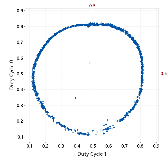
I rescaled the duty cycle data using custom upper and lower limits and then transformed those to sin(AWA) and cos(AWA) which are plotted in Figure 16. The discrepancies between the plotted points and the ideal circle shows the calibration errors of the system. Nexus provides an 8 point table of calibration correction values (0 to 360 degrees by 45 degrees) that are expected to correct for these errors.
 versus cos(AWA).")
The Nexus AWA values were not logged when the data used in Figures 15 and 16 were collected so I had to use a different data set to compare the AWAs reported by the Nexus to those determined by the duty cycle method. Figure 17 shows AWA reported by the Nexus versus AWA calculated from atan2() of the rescaled, corrected duty cycle values using the previously determined factors. The two methods are in good agreement and the noise can be dealt with using a low pass filter. Given a larger, more complete data set, it should be possible to determine the transformations necessary to convert the raw sensor data collected by the Arduino into accurate and precise AWA values.
 of Duty Cycle methods.")
Conclusions
This project has presented hardware and firmware to collect raw Nexus sensor data using an Arduino while simultaneously collecting NMEA data from the Nexus server and a Garmin GPS. It has also been confirmed that it is possible to correlate the raw sensor data to the values reported by the Nexus system. With more data, and more analysis, it should be possible to replace the Nexus server with an Arduino-based system that provides more flexibility and control by the user.