The idea for the project came when I was considering using power over ethernet (POE) for another project and wanted to understand how to implement it in something simpler beforehand. At around the same time I came across the affordable stack light units and thought it would be useful for a few applications so decided to merge the two and build a POE powered version. The two main application areas are either status reporting, for things like system availability monitoring, or continuous integration. The other application area is for use in theatrical lighting systems like those used in the Student Robotics competition or for my portable bridge setup for the game Artemis.
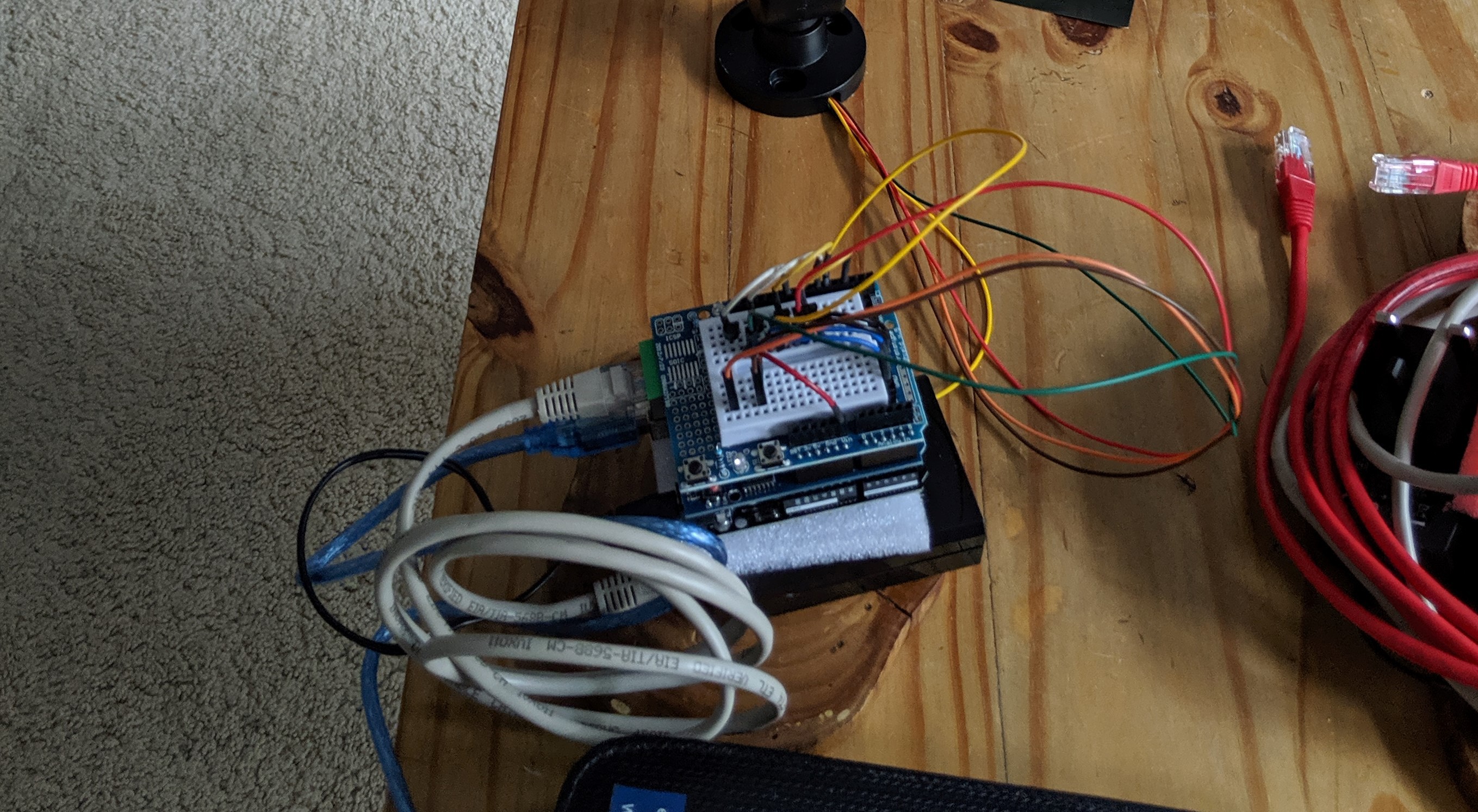
The first iteration was a proof of concept largely consisting of off the shelf blocks. An Arduino with an ethernet shield were used as the control system and powered using A POE splitter. A prototype shield containing the transistors for switching the light was then mounted on top.
With this setup the initial firmware was prototyped and got to a functioning state, however, the lack of flash and ram on the chip limited the amount of features that could be enabled at once. The other limitation of this version was that only one segment could be fully lit at a time due to a single current limiter built into the stack light. Despite this the prototype was useful so development was started on a customised board to control the light.

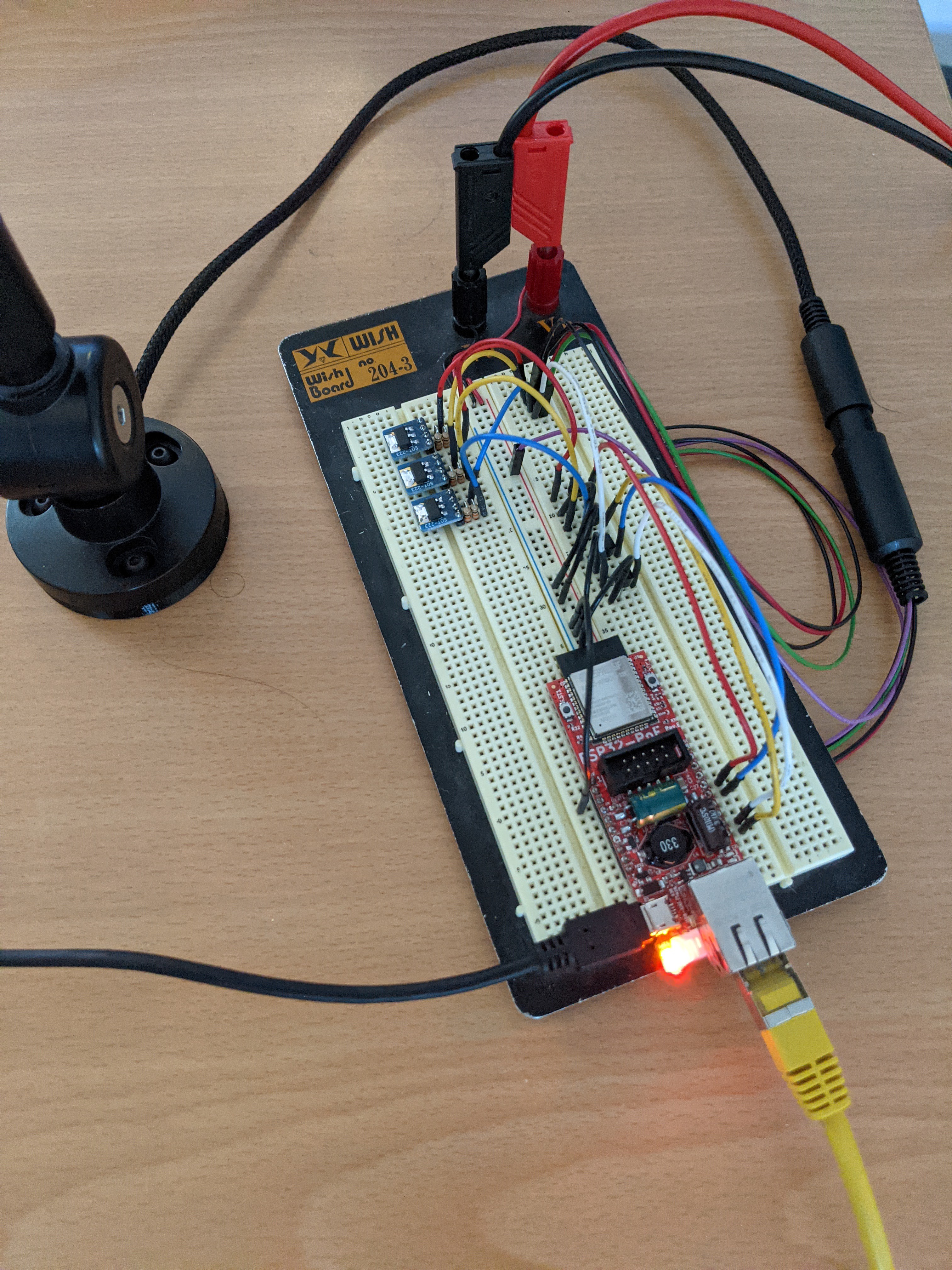
Initial thoughts were to design the controller to fit into the base of the light. Trying to do this at the same time as fixing the issues with the first prototype proved time consuming and resulted in the project being shelved for a while. After the hiatus a new plan was created to reduce complexity and get the project moving again by focusing on its core goals. The integrated base idea was scrapped and instead the controller would be placed in an off the shelf enclosure in order to remove the mechanical design aspect of the project and reduce the size constraints on the PCB. The led control was simplified, rather than using a controlled current LED driver, the current limit in the light would instead be duplicated for each channel, this takes more board space, but without the limitation of fitting the design into the base this was no longer an issue. Finally the Arduino based control logic was swapped out with an ESP32 based system as this resolved the processor issues and simplified the network connectivity component of the design. In order to test these plans a simplified breadboard prototype was created with an ESP development board. Unlike the first design, this targeted testing the planned alterations and pinout combination would work before completing the PCB design. It also allowed for continued software development while the PCBs were being produced.

With the design tested using the second prototype the PCB design was completed and ordered. After debugging a few issues with the board the software from the second prototype was able to be flashed onto the board and the work to complete the software could begin.
 Tyler Ward (Scorpia)
Discussions
Become a Hackaday.io Member
Create an account to leave a comment. Already have an account? Log In.