 gilphilbert
The SMT work wasn't anywhere near as hard as I was expecting. Having the SMT stencil really helped as it put the correct amount of paste down and it really helped keeping the components in place as I put them on the board. I did have the hot air gun power up too hard at first and sprayed my components around a bit, but after I fixed that it went pretty well. I had a tiny amount of reflow - two resistors that were pretty close had joined at one end.
I built the power sections first and measured everything. 4.98V and 3.3V on the nose, so all good. I soldered on the ESP32, switches and resistors and the SD card slot and flashed the MCU. A quick test showed that the SD card was behaving a little oddly, but nothing serious it was working - I was just getting some spurious errors. Nothing serious, so I decided to put that on my TODO list. I wish I hadn't...
Next I soldered on the DAC stage. Again, this wasn't too bad - I had to remove a little extra solder that was bridging two the IC pins but that was it. I powered it back up and connected it to the amplifier stage on my previous prototype as I hadn't built the amplifier stage yet. This was a smart move, as it turned out.
What did I get? HISSSSSSSSSSSSSSSSSSSSSSSSSS. Not good. Not only that, but now the ESP's serial was behaving strangely with some garbage characters and I couldn't get the i2c communication to work at all. The display was working nicely though.
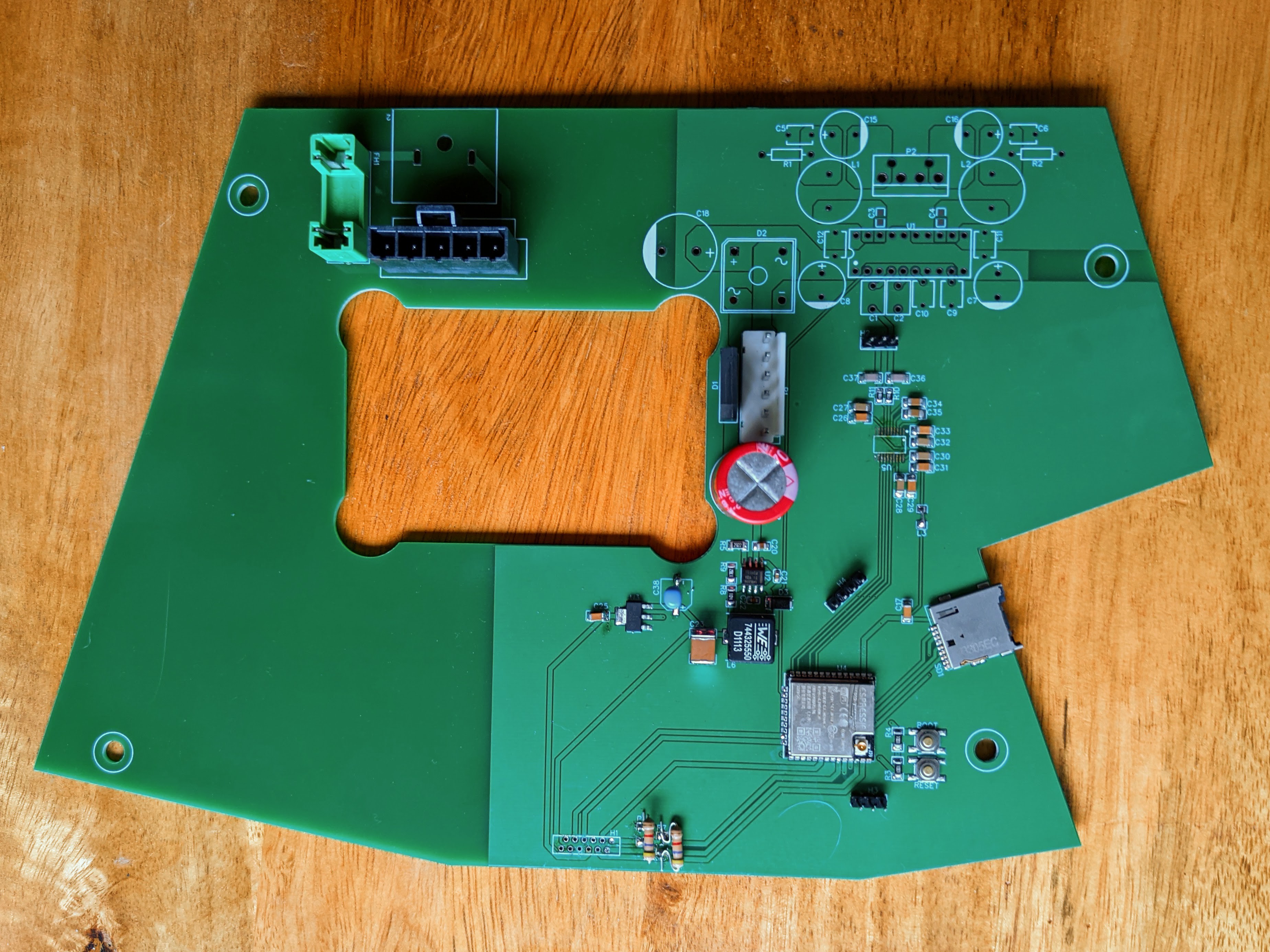
I've spent hours fiddling with this new prototype. I removed and re-soldered the ESP32, even trying a different module in case I had burned out the first one by heating it for too long. I removed the PCM5102A and resoldered it, but still I was getting tons of static. I removed the ESP32 and tried using the board as a very large DAC module, but nothing. I swapped my 1K i2c pullup resistors for 4.3K in case they were too strong (with the FPC cable they shouldn't be...) and I swapped out the input capacitor for the 3.3V LDO in case that was an issue. Here's the board after all that work:
In the end, I've come to a single conclusion: the power supply is causing issues. It's the single item that could cause such widespread issues.
It's very frustrating and I can't really track down the issue as I don't have an oscilliscope. I may have to buy one to track down the issue. The documentation for the LMR14020 isn't wildly clear and while I'm no fool, I can't figure out some of their calculations which don't seem to add up. Perhaps I'll try a different 5V switching regulator design. Back to the old prototype for now while I try to work out how to solve this issue.
Discussions
Become a Hackaday.io Member
Create an account to leave a comment. Already have an account? Log In.