 Michael Perrone
Now that I've described how Semisolid Metal Printing can be
achieved, here's the progress so far in reducing it to practice:
Firstly, making one’s own filament is surprisingly easier than I
expected: equipment exists on the market for jewelers to melt metal
and draw it into wire for a couple hundred dollars. These already
quite refined technologies, with not much optimization or
modification, could become something similar to the filastruder, but
for metal. Due to wire drawing technology it would be even easier
than with plastics to make wire with a very consistent diameters, because the final forming stage happens completely in the solid state instead of in a molten state. I should mention though that while wire feed is convenient, it might not be necessary if you have other ways to control extrusion (in my case capillary pressure equilibration plus magnetohydrodynamic motors). For example, it would be extremely inexpensive to meter in metal shot at regular intervals with a device similar to a gumball machine.
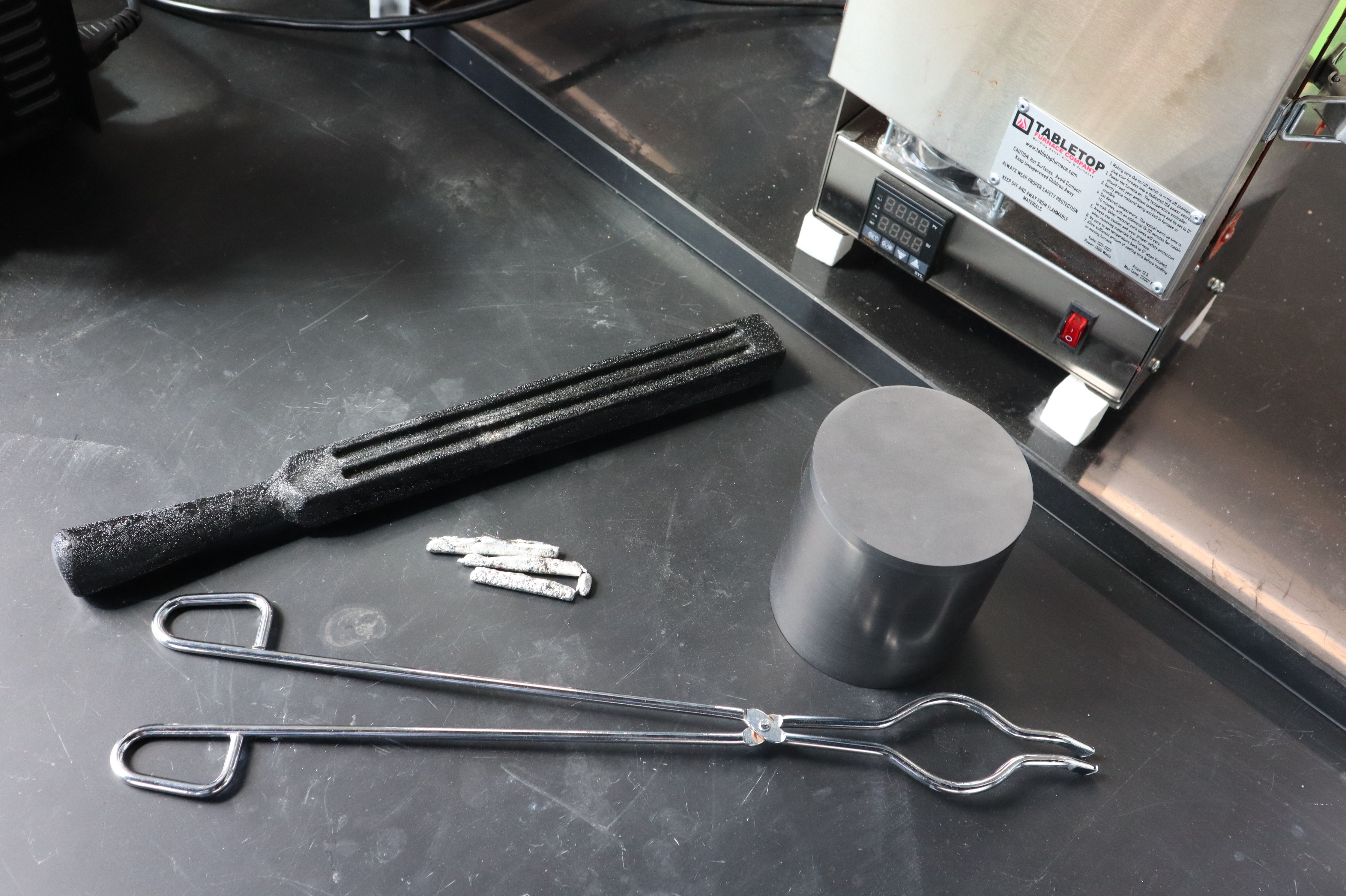
Tabletop Furnaces makes muffle furnaces well suited to preparing molten metal to draw wire from. They cost roughly $500 and if carefully handled, they can last a long time I can melt alloys from scratch this way at reasonably high temperatures, but if you have pre-made alloy shot or ingots, ~$25 metal melting pots for making lead shot are common online. Crucibles, tongs and casting molds can be used to cast long bars which can be subsequently drawn into wire. For large scale production, continuous casting seems to be the standard technology.
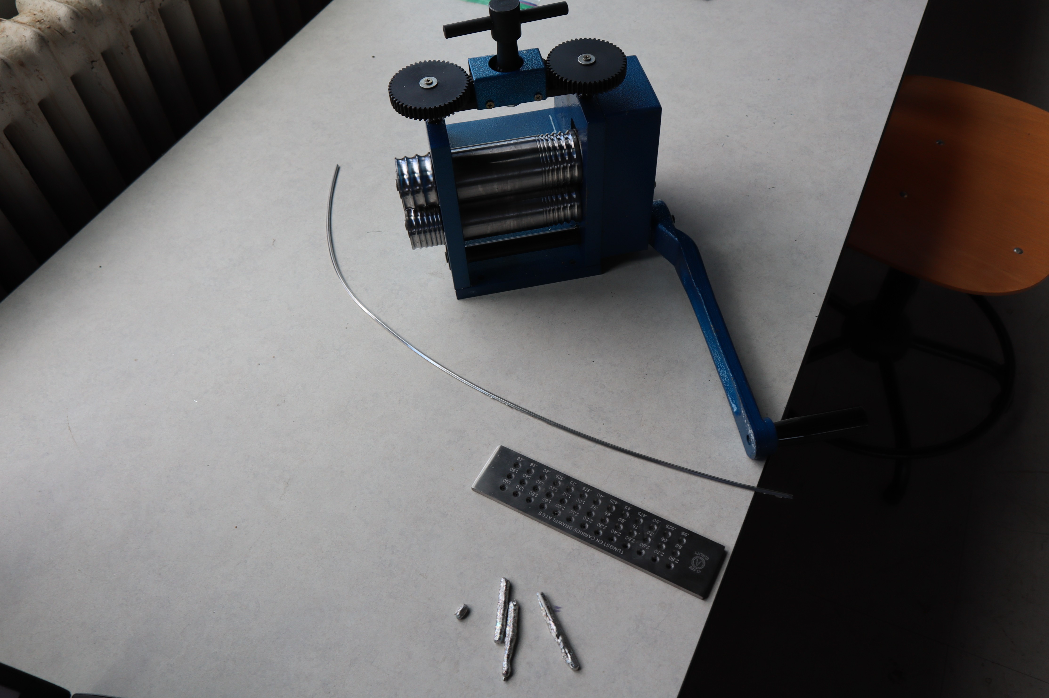
Here we have some prototype metal alloys in various stages of being drawn into wire, as well as a wire drawing plate and a rolling mill. At the small scale, wire drawing plates or wire drawing dies are standard for finishing wire for jewelry making, and miniature wire rolling mills can press the cast long ingots into wire thin enough to use in the drawing plate. Because of the jewelry industry, these technologies have existed for a very long time, and these are likely the easiest technologies to adapt to making filament for metal printing as a continuous process. Really the bottleneck will be the casting procedure, which for jewelry making, is not a continuous process.
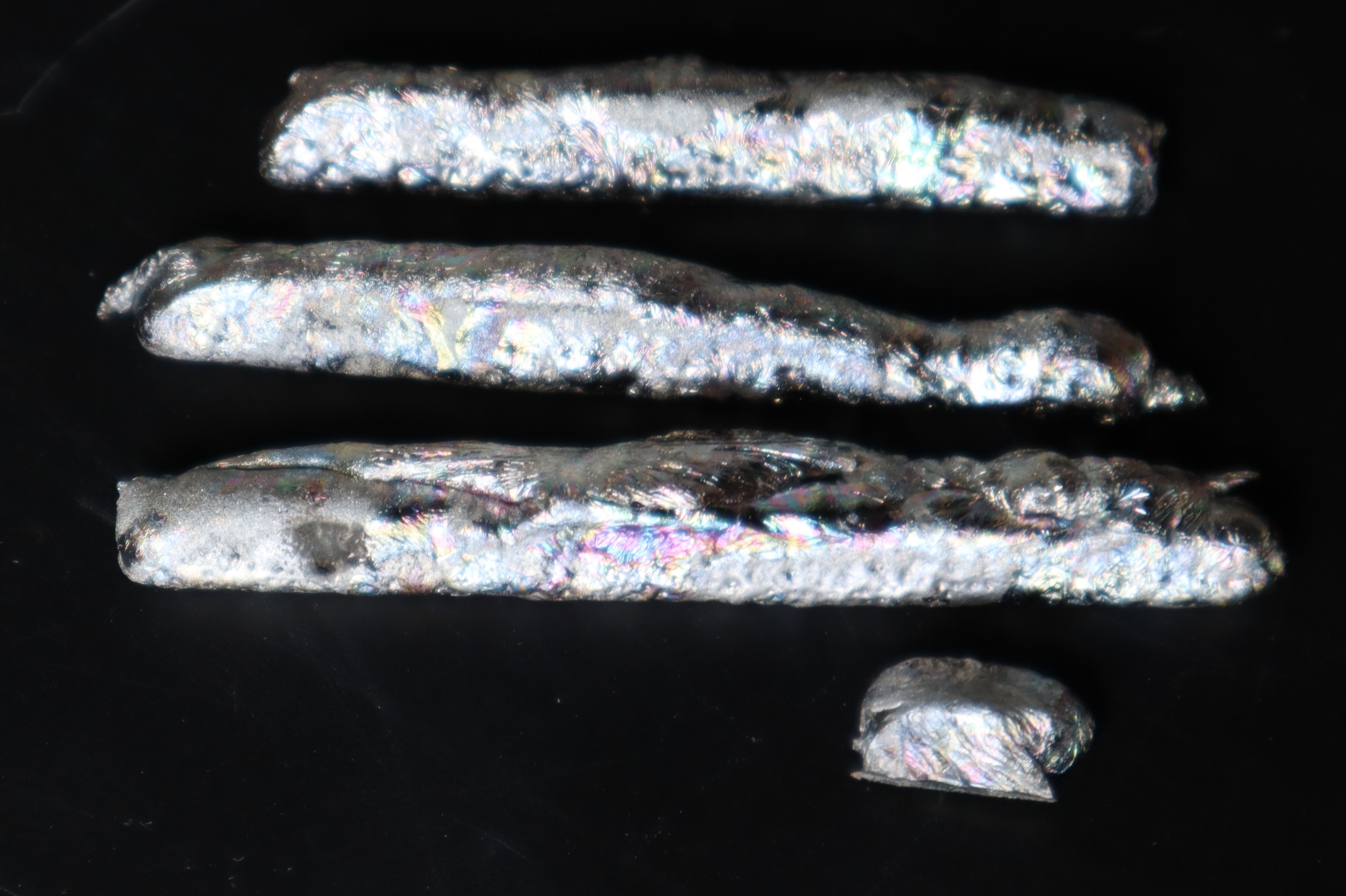
Here is a closeup of some of the experimental alloy castings: I just liked the iridescent oxide layers on this particular one and thought others might too. Tin-bismuth and tin-silver-copper alloys can be used based on solders with good results, but for the best combinations of low melting point, acceptable price (I was surprised to learn that tin is more expensive per kilo than titanium!) and high structural strength at room temperature, tin-zinc alloys are the way to go. There are ways to adapt this printing technology to copper, iron and aluminum alloys in the future, though those might ultimately have a system cost similar to a low end CNC, with tighter specs, enclosures, emergency stops, possibly inert atmospheres, etc. It would still beat other metal printing technologies by miles,
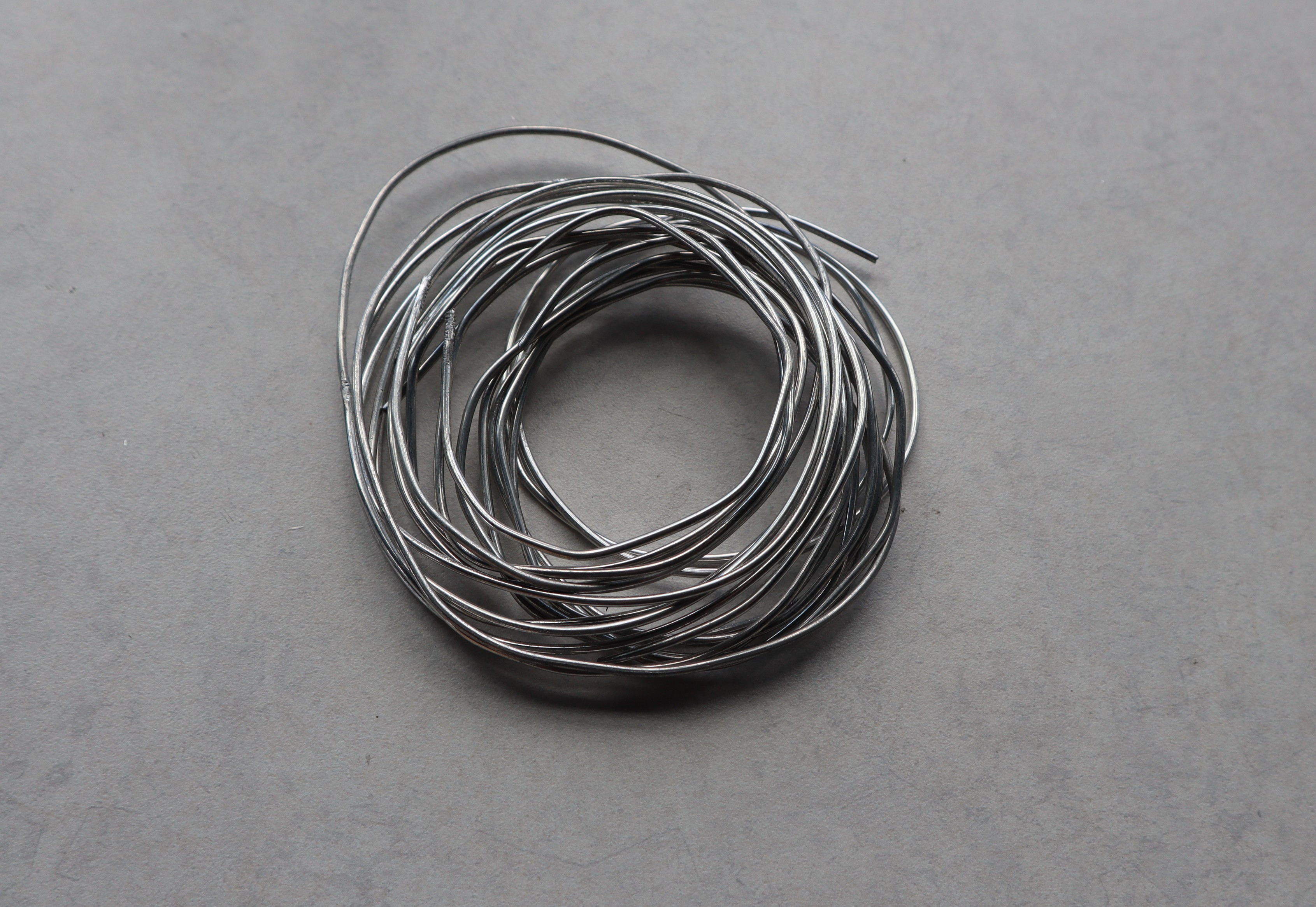
Here’s some of the completed wire/filament for extrusion. Its surface finish is smooth and the wire diameter is extremely consistent; perhaps equal to or better than industrial plastic filament extrusion precision. That’s because wire drawing is done in the solid state, making it far easier to control.
Now let's finally talk about the extrusion system, I modeled these parts for an extrusion system using a bondtech extruder and attaching to an old Prusa Mendel i2 I had lying around. No need to redesign the motion system or filament feeder, since those have already been developed. We're focusing completely on proving out the hotend functionality here

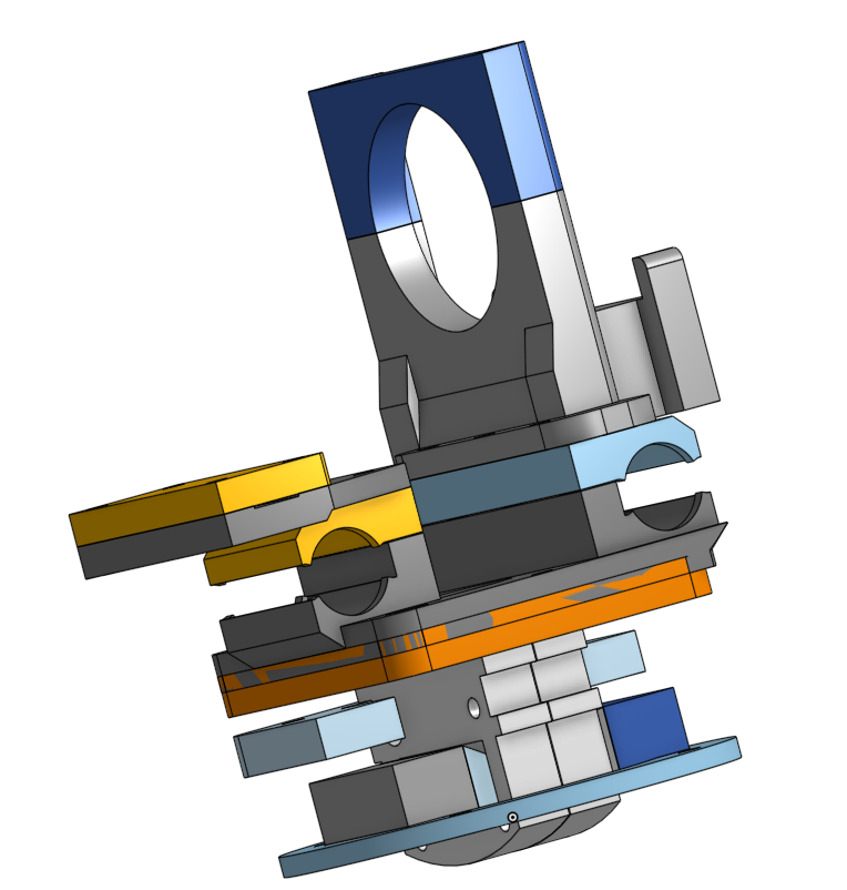
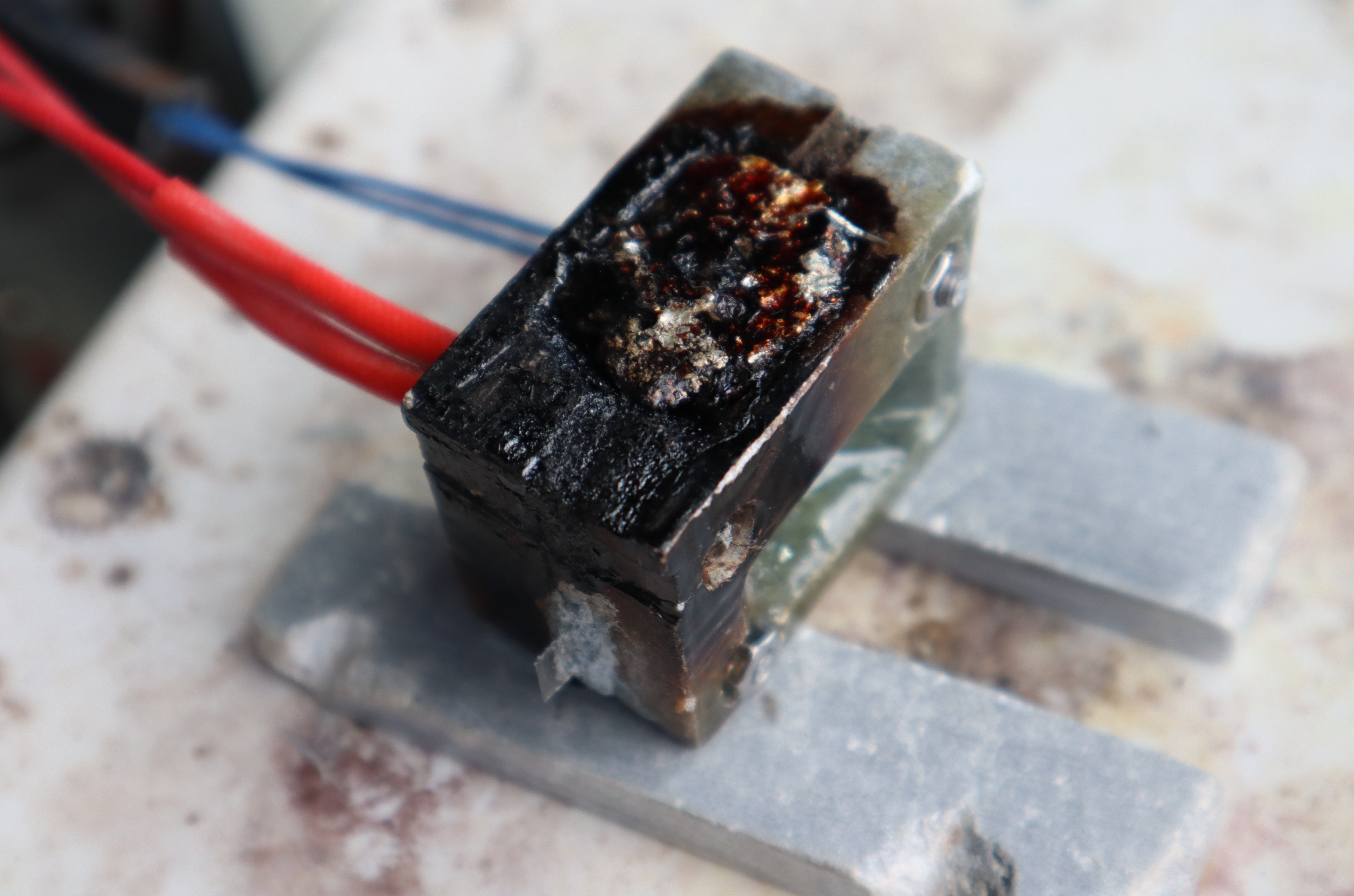
Funny story, the guy who was going to machine the hotend blocks for me canceled at the last second, so in an effort to get the system working for Midwest RepRap Fest, I hand carved a bunch of hotend blocks out of soapstone. Soapstone turned out to be surprisingly resistant to thermal shock and just tough enough for my application. Anyways Adding MHD functionality to the heater block complicates things quite a bit; a normal E3D block is maybe 1/4th the size this one ended up being. The rectangular cavities are where the polepieces of the magnetic concentrator fit in. Ideally they don't make physical contact with the soapstone and/or are insulated. The guts of the MHD system are these wicks and electrodes. For the tin-zinc base alloys I found a pure iron wick works extremely well, and also helps to further concentrate the magnetic field. The electrodes are molybdenum, which is quite wettable by tin-zinc if it has had the proper surface treatment, but not otherwise wettable and certainly not soluble. If memory serves, there are papers involving adding molybdenum nanoparticles to solders as a grain refining agent, and not even the nanoparticles dissolve appreciably over time. Wetting on ferrous alloys is still better though, so I still prefer that for the wick. The wick just barely sticks out the bottom of the heater block, and that is plenty to have the required temperature drop into the semisolid range during printing.
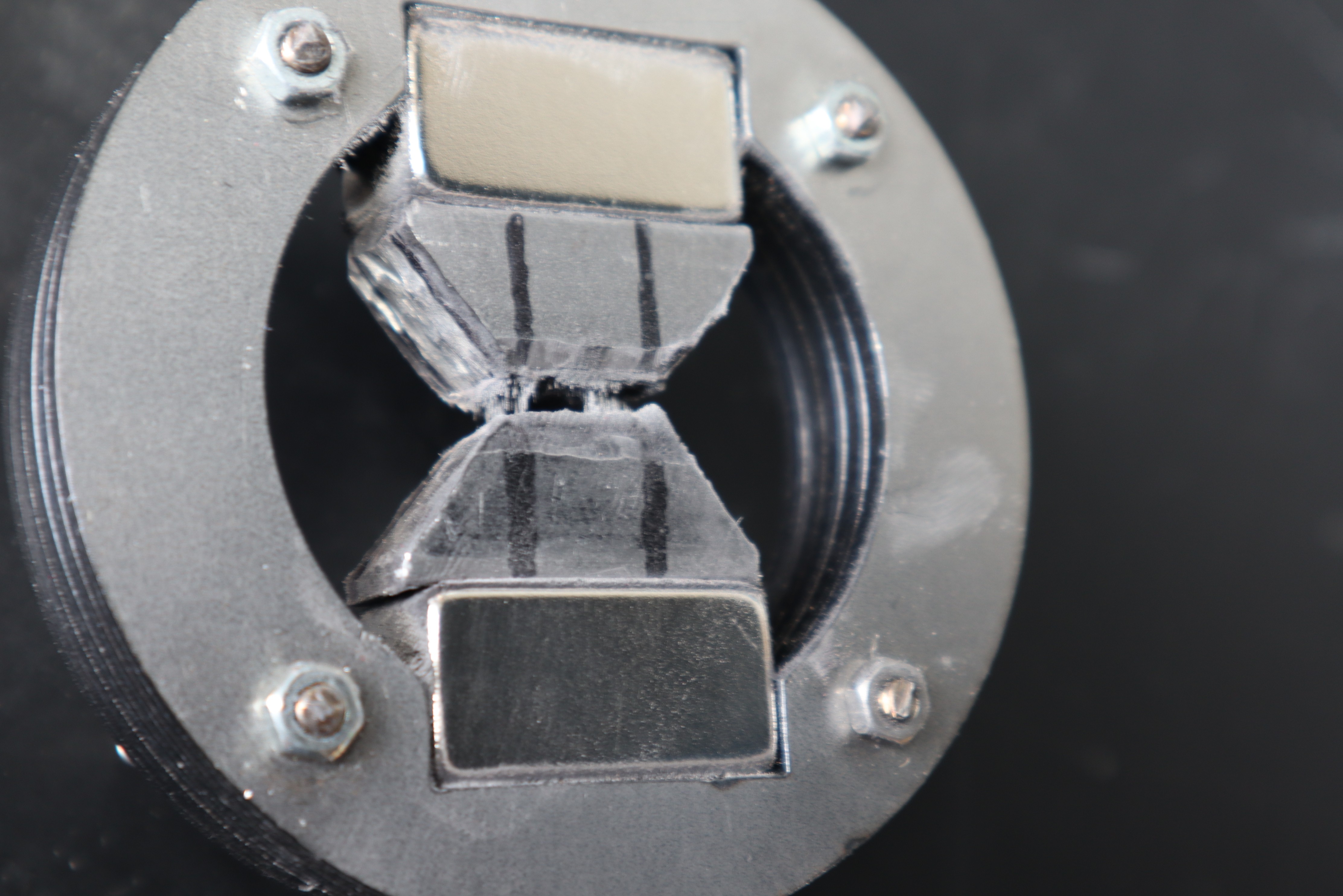
Here's the magnetic yoke that's meant to go around the hotend block, with a few iron filings to show off the field lines through the center. It was not easy to machine soapstone thin enough to fit through that gap
Here's the finished prototype heater block: it has a melt reservoir in the top of it with a low chromium stainless steel "sponge" to keep the melt pool in place and balance capillary forces. The bolts and nuts are titanium, so that they do not draw any magnetic field around the pole pieces but are still plenty strong enough to clamp the halves of the heater block together. The "gasket" is Cotronics castable silicon carbide; pretty convenient stuff to work with for anything involving high temperatures. Before joining the soapstone heater blocks with the castable ceramic, I coated them with a thin layer of epoxy. I learned this trick from some friends at a larger company: it allows you to join ceramics with different thermal expansion coefficients quite reliably, because the epoxy takes all the strain when the system is at temperature and it can do so repeatedly. The ideal situation is to just make it all out of castable ceramic of course. The thermistor are standard E3D stuff for compatibility.
Sadly, I didn't get it working in time for Midwest RepRap Fest: the E3D heater couldn't get the thing above 200C when it needed at least 240C to function, but I learned from this prototype and once Midwest RepRap Fest is over, it's on to V2: less surface area, more insulation, a more powerful heater, and since I won't have a tight deadline, I'll take my time and cast the hotend sections all out of silicon carbide. Once I print something with it, then I'll worry about adding the ability to change out the brush as a consumable. If anyone has thoughts or recommendations about what the next steps should be, feel free to leave a comment on the project page. Thanks for the feedback!
Shoutout to Cotronics by the way: their high temperature castable ceramics are really awesome for any high temperature fun.
Discussions
Become a Hackaday.io Member
Create an account to leave a comment. Already have an account? Log In.