 Alex M Sunny
UV BOT WORKING VIDEO
UV BOT APP WORKING
Wio terminal
We are using the Wio terminal which has many inbuilt sensors. The Wio Terminal is a SAMD51-based microcontroller with Wireless Connectivity supported by Realtek RTL8720DN that’s compatible with Arduino and MicroPython. It runs at 120MHz (Boost up to 200MHz), 4MB External Flash, and 192KB RAM. It supports both Bluetooth and Wi-Fi providing the backbone for IoT projects. The Wio Terminal itself is equipped with a 2.4” LCD Screen, onboard IMU(LIS3DHTR), Microphone, Buzzer, microSD card slot, Light sensor, and Infrared Emitter(IR 940nm). Really cool features in one single device right. In our case, it acts as a wifi access point and we can connect the raspberry pi and our Virtual machine to a single access point. The inbuilt display will show the time and other messages.
We are using the IMU sensor, inbuilt temperature sensor, and buzzer in the WIO terminal to detect a collision, overheating and it alerts through buzzer as well as our mobile app.
We are adding the UV light sensor to detect and get the feedback if UV light is ON or OFF.
The WIO terminal is also connected to the relay to control the UV lights. The WIO terminal acts as an access point as well as a server. So that we can control the relay from
UV SENSOR
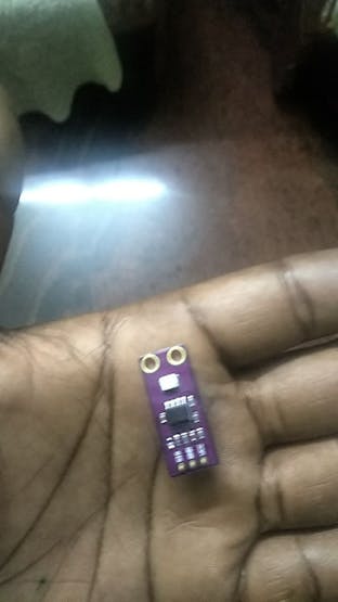
Uv sensor photo
It uses a UV photodiode, which can detect the 240-370nm range of light. The signal from the photodiode is a very small level, in the nano-ampere level, hence an opamp to amplify the signal to a more Manageable voltage-level.
Use this basic code to test it
//input this code to test UV sensorvoid setup() {Serial.begin(115200);pinMode(A8, INPUT);}void loop() {int uvsensor = analogRead(A8);Serial.print("UV intensity: ");Serial.println(uvsensor);delay(50);}
DHT sensor
There is a thermistor. There is also a very basic chip inside that does some analog to digital conversion and shows a digital signal with the temperature and humidity. The digital signal is fairly easy to read using wio terminal. Here we are using it as a safety feature. The internal temperature of the robot is being measured here. If it is getting really high the complete system will shut down.
UV light
We are using 20w unit 2ft Sanyo Japan UVC lamp with a full assembly which provides an area coverage of 70 sqft which is sufficient for our application. You can refer to these articles to find out more regarding the disinfection properties of UVC light.
- https://www.ncbi.nlm.nih.gov/pmc/articles/PMC6801766/
- https://www.who.int/emergencies/diseases/novel-coronavirus-2019/advice-for-public/myth-busters?gclid=EAIaIQobChMIsPPlg4K-6wIVU7eWCh2E7QtREAAYASAAEgK7HfD_BwE#uv
PIR sensor
PIR sensors allow you to sense motion, almost always used to detect whether a human has moved in or out of the sensors range. They are small, inexpensive, low-power, easy to use, and don't wear out But it is a little inaccurate in our case we have to use Contact-less Infrared Thermopile Sensor with OpenCV to get more accurate data for human detection. We are working on the Thermopile sensor we will update in this tutorial really fast.
We are running the access point in the Realtek board and sensors are working from the wio terminal.
You have to burn the bootloader to get access to the Realtek board in Wio terminal, follow this link to do it.
This is the code we used.
#include <WiFi.h>// Current timeunsigned long currentTime = millis();// Previous timeunsigned long previousTime = 0;// Define timeout time in milliseconds (example: 2000ms = 2s)const long timeoutTime = 2000;String header;// Auxiliar variables to store the current output stateString output5State = "off";String output4State = "off";const int output5 =5;const int output4 = 4;char ssid[] = "UV bot"; //Set the AP's SSIDchar pass[] = "12345678"; //Set the AP's passwordchar channel[] = "1"; //Set the AP's channelint status = WL_IDLE_STATUS; // the Wifi radio's statusWiFiServer server(80);void printWifiStatus() {// print the SSID of the network you're attached to:// Serial.println();// Serial.print("SSID: ");// Serial.println(WiFi.SSID());// print your WiFi shield's IP address:IPAddress ip = WiFi.localIP();//Serial.print("IP Address: ");// Serial.println(ip);}void setup() {//Initialize serial and wait for port to open:Serial.begin(115200);Serial1.begin(115200);pinMode(output5,OUTPUT);pinMode(output4,OUTPUT);while (!Serial) {; // wait for serial port to connect. Needed for native USB port only}// check for the presence of the shield:if (WiFi.status() == WL_NO_SHIELD) {//Serial.println("WiFi shield not present");while (true);}String fv = WiFi.firmwareVersion();if (fv != "1.0.0") {// Serial.println("Please upgrade the firmware");}// attempt to start AP:while (status != WL_CONNECTED) {//Serial.print("Attempting to start AP with SSID: ");//Serial.println(ssid);status = WiFi.apbegin(ssid, pass, channel);delay(10000);}//AP MODE already started:// Serial.println("AP mode already started");//Serial.println();server.begin();printWifiStatus();}void loop(){WiFiClient client = server.available(); // Listen for incoming clientsif (client) { // If a new client connects,Serial.println("New Client."); // print a message out in the serial portString currentLine = ""; // make a String to hold incoming data from the clientwhile (client.connected()) { // loop while the client's connectedif (client.available()) { // if there's bytes to read from the client,char c = client.read(); // read a byte, thenSerial.write(c); // print it out the serial monitorheader += c;if (c == '\n') { // if the byte is a newline character// if the current line is blank, you got two newline characters in a row.// that's the end of the client HTTP request, so send a response:if (currentLine.length() == 0) {// HTTP headers always start with a response code (e.g. HTTP/1.1 200 OK)// and a content-type so the client knows what's coming, then a blank line:client.println("HTTP/1.1 200 OK");client.println("Content-type:text/html");client.println("Connection: close");client.println();// turns the GPIOs on and offif (header.indexOf("GET /5/on") >= 0) {//Serial.println("GPIO 5 on");output5State = "on";digitalWrite(output5, HIGH);//Serial.print("5");} else if (header.indexOf("GET /5/off") >= 0) {// Serial.println("GPIO 5 off");output5State = "off";Serial.print("7");digitalWrite(output5, LOW);} else if (header.indexOf("GET /4/on") >= 0) {//Serial.println("GPIO 4 on");output4State = "on";digitalWrite(output4, HIGH);} else if (header.indexOf("GET /4/off") >= 0) {//Serial.println("GPIO 4 off");output4State = "off";digitalWrite(output4, LOW);}client.println("<!DOCTYPE html><html>");client.println("<head><meta name=\"viewport\" content=\"width=device-width, initial-scale=1\">");client.println("<link rel=\"icon\" href=\"data:,\">");// CSS to style the on/off buttons// Feel free to change the background-color and font-size attributes to fit your preferencesclient.println("<style>html { font-family: Helvetica; display: inline-block; margin: 0px auto; text-align: center;}");client.println(".button { background-color: #195B6A; border: none; color: white; padding: 16px 40px;");client.println("text-decoration: none; font-size: 30px; margin: 2px; cursor: pointer;}");client.println(".button2 {background-color: #77878A;}</style></head>");client.println("<h1>UV BoT</h1>");client.println("<p>UV Light status " + output5State + "</p>");// If the output5State is off, it displays the ON buttonif (output5State=="off") {client.println("<p><a href=\"/5/on\"><button class=\"button\">ON</button></a></p>");}else {client.println("<p><a href=\"/5/off\"><button class=\"button button2\">OFF</button></a></p>");}client.println();break;}else { // if you got a newline, then clear currentLinecurrentLine = "";}} else if (c != '\r') { // if you got anything else but a carriage return character,currentLine += c; // add it to the end of the currentLine}}}// Clear the header variableheader = "";// Close the connectionclient.stop();// Serial.println("Client disconnected.");// Serial.println("");}}
In the wio terminal run this code to get access to the inbuilt sensors, PIR, UV sensor and to control the UV lights by relay.
Wio Terminal working
Communication with Realtek board and Wio terminal board
Use this code to test the communication
void setup() {RTL8720D.begin(115200);Serial.begin(115200);}void loop() {if (RTL8720D.available()){int inbyte = RTL8720D.read();Serial.write(inbyte);}}
MOTORS
The initial plan was to use two NEMA 34 motor with 85KGCM Torque and use two DM860A2 motor drivers. But one of them was not working properly and so we changed our motors and drivers.So in this project, we will be using four wiper motors and two BTS7960 IBT2 motor divers instead. These motors can carry a sufficient load of our robot and control and coding is simple too.

photo of burned motor driver

1 / 2 • battery , invetor final connection.
Charging circuit
The robot identifies the charging port using path planning and comes and charges once every 5 hours. There are two rods on the robot and there are electrodes in the charging port which aligns properly. There is a magnetic reed switch which gets closed when the robot arrives.

charging port for robot
Code
#include <UTFT.h>// Declare which fonts we will be usingextern uint8_t BigFont[];UTFT myGLCD(ILI9481,38,39,40,41,42);// ElecFreaks TFT2.2SP Shield// constants won't change. They're used here to set pin numbers:const int Reedswitch = 11; // the number of the reedswitch pinconst int ledPin = 10;const int relay = 9; const int statusled = 12; // variables will change:int buttonState = 0; // variable for reading the pushbutton statusvoid setup() { randomSeed(analogRead(0)); // Setup the LCD myGLCD.InitLCD(); myGLCD.setFont(BigFont); digitalWrite(statusled, HIGH); // initialize the LED pin as an output: pinMode(ledPin, OUTPUT); pinMode(relay, OUTPUT); // initialize the pushbutton pin as an input: pinMode(Reedswitch, INPUT);}void loop() {// Clear the screen and draw the frame //myGLCD.clrScr(); // read the state of the reedswitch value: buttonState = digitalRead(Reedswitch); // check if the reedswitch is closed. If it is, the buttonState is HIGH: if (buttonState == HIGH) { // turn LED on: digitalWrite(ledPin, HIGH); digitalWrite(relay, HIGH); myGLCD.clrScr(); myGLCD.setColor(255, 255, 255); myGLCD.setBackColor(255, 0, 0); myGLCD.print("UVBOT is Charging!", CENTER, 93); } else { digitalWrite(ledPin, LOW); digitalWrite(relay, LOW); myGLCD.setColor(255, 255, 255); myGLCD.setBackColor(0, 0, 255); myGLCD.print("Charging circuit is ON!", CENTER, 93); delay(20); }}
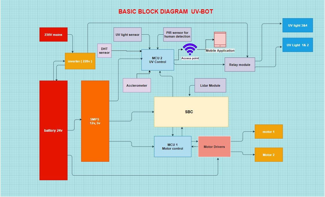
Blockdiagram

Charging port
Components
- ArduinoMega: It acts as the controller for the charging circuit.
- Relay:To safely switch on the circuit if the robot arrives and protects others from accidentally touching it.
- Reed switch: It is a magnetic switch it will be closed when magnets get in contact.
- Status LED: To see the status.
- Touch Screen It is used to show the status on the screen. We are using a 3.5-inch touch screen shield for Arduino Mega.
The electrodes on robot will align with the electrodes in the charging station.

Electrods on the charging station

electrods on robot
Fabrication
We have used Aluminum for fabrication for the case since it is lighter.
Top Part
Holds a mirror to reflect light and holds the UV light.

Top part

top part top view
Bottom Part
It holds the Motor, Battery, and Inverter.

Bottom part frame
Middle part
The middle part holds the Wio terminal and the safety circuits.

Middle portion frame
Charging circuit Fabrication

Charging port frame
Motors
Motor wheels were cut using Lathe and were connected to the motors and have a diameter of 12 cm.

motors connected to the wheel.
Base

How to use a robot?
- Switch on the Robot. It connects to the wifi of the WIO terminal.
- Control the Robot through and Map the room.
- Save the MAP.
- Switch it to Autonomous mode.
- You can switch on the UV light with the app.
- You can see the status of the UV robot in the app.

UV BOT
UV App
We have used a UV application to switch on and of the LED and to show the other status like UV bot is down or UV bot is charging. You can download the app from here.
UVBot Working
BOM-Bill of materials

Bill of materials
Robot Characteristics
- Robot weight: 36 pounds
- Robot Cost: 2300 USD
- Disinfection area: 70 sqr meters
- Running time with a single charging cycle. :5 Hours
- Height of the robot: 150cm
- Width of the robot: 52cm
Future Plan for version 2
- Omnidirectional wheel
- Better processor
- Better motors with feedback
- Better sensors for human detection.
- Use PCBs
- Proper weight distribution