 Bacon8tor
**TLDR** I reverse engineered the PCB inside a Logitech DFGT, so that you could use aftermarket wheels, add buttons but not have to use any external usb device, or solder wires to each button individually. These aftermarket buttons would be read just as the stock wheel, meaning plugged into a console the PS button or Xbox button would still function normally(** I don't own a console to test this but I'm pretty sure about it), on PC not a huge deal cause you usually can map whatever button to whatever. For PC simmers with a Logitech wheel means you can add buttons or even a button box(if you remove the stock wheel controls) but not have to add more cables to your setup and all buttons would be treated as stock.
Let me begin this is my first post of one of my projects, tbh I usually get a project working just good enough for me and don't release it cause I know there are issues. In this case I feel like maybe just maybe someone may find this of use or interest. Cause this completely was accidental/unexpected. First time I went down a rabbit hole and actually found the other side..
I recently purchased a new Logitech G920(primarily for the pedals but after a lot of driver issues and force feedback actually using the new wheel now), this is to replace my old bought used Logitech Driving Force GT. Which is still in great working order, have always been surprised how well this wheel has held up over the years, but now since I had a backup/replacement in the G920 it allowed me to dive into some mods I had been wanting to do. Mainly add a quick attach/release mount to the wheel, so I could attach aftermarket steering wheels, this thing https://www.thingiverse.com/thing:4680058 made quick work of that, and even allowed for a connection to still be made. The use case in his video which is attaching the stock wheel back to the base, the buttons would only work with the stock wheel. Not to say there is not another way to retain the factory buttons, this video the board from the wheel is removed and placed in he base then wires to each button are soldered and ran to the wheel, which great works factory buttons, but requires a full disassembly, a lot of soldering some of which like for start and Select you have to solder on the pads. As well as just adding an Arduino Micro/Leonardo and making a whole new controller, which again works great but now you have another USB device. Honestly I would have gone one of these routes myself as I have tinkered with Arduinos for years and fusion 360 but have absolutely no formal education in electronics/engineering. But then I decided to just look at the buttons and noticed the same three chips and said what the heck lets google it.....
Turns out the chips is a 74HC165(D), a common 8-bit Shift Register, and instantly recognized it as remembering using them with a 7 segment display. I am going to skip the step by step because honestly there was none, I just got my multimeter out and started poking around. I first identified ground and power, as I figured prolly best to know where those are to not fry anything. Not sure if this is a common thing but threw me for a loop for a little that ground was the red wire and 5v was the brown wire, after triple checking just with the wheel unplugged and continuity test, plugged in and measure the voltage and indeed found 5v and ground with out frying anything, WOOHOO. After this I knew I needed to find where the Serial output and Clock input as my idea was to grab an Arduino Nano and see if I could read the buttons, to me this meant I could make my own button board and feed it back to the Logitech stock board and emulate(but not really emulating cause I am giving it the same data just different board). I started from the plug on the pcb then started probing(again wheel is unplugged and using continuity test) to trace what goes where on the plug to the chip closest to the plug. I then referenced the data sheet for the 74HC165 to see what pin it was, and what it did. After awhile of testing and double testing I was pretty sure I had the Serial out, Clock Input, and Active Low.
Hindsight, I realize I could have trusted the data sheet and I would have already known what pins but looking at datasheets is something new to me I have been doing it more and more as you find specs or abilities that may not be well known, and I found the more you look at them the more you understand.
I digress, found the three wires I believe I needed, got my Arduino Nano, loaded up a sample sketch I found that was for reading a single 74HC165. I really wanted to test at this point if I was on the right track or not, I was hoping to see any change in the output based on me hitting the buttons. Plugged in the Nano uploaded the test sketch, opened the monitor and it began spitting out eight 0's at me. Ok so at this point I'm surprised I haven't gotten any smoke, that's a win, and getting something output means time to hit some buttons and see if something changes. After a couple pokes around I got a 1 in the mix!!! So this is where I got excited, cause I knew I was reading the chip correctly and getting outputs.
Next question that immediately presented itself, is how do I read the other two chips? I have never used more than one 74HC chip before(and after a look in my parts bin I had never used a HC165 - I used the HC595 which is for outputs, which DUH! I was outputting to the 7 segment). So now I looked around for an example reading multiple of the chips and trying to understand how it works. At this point I was really in unknown territory, and was honestly taking a shot in the dark, I found an sketch that used SPI and read 2 chips, so figured that's a good start and well it worked I was now getting 2 sets of 8 bits, didn't really understand how but I knew I was getting what I was expecting. I then edited the sketch and anywhere there was something for chip 1 and 2 I just made a 3, uploaded, BAM now 3 sets of 8-bits. Started pushing buttons and seeing all the 1's and 0's changing , and as expected each button changed a different bit.
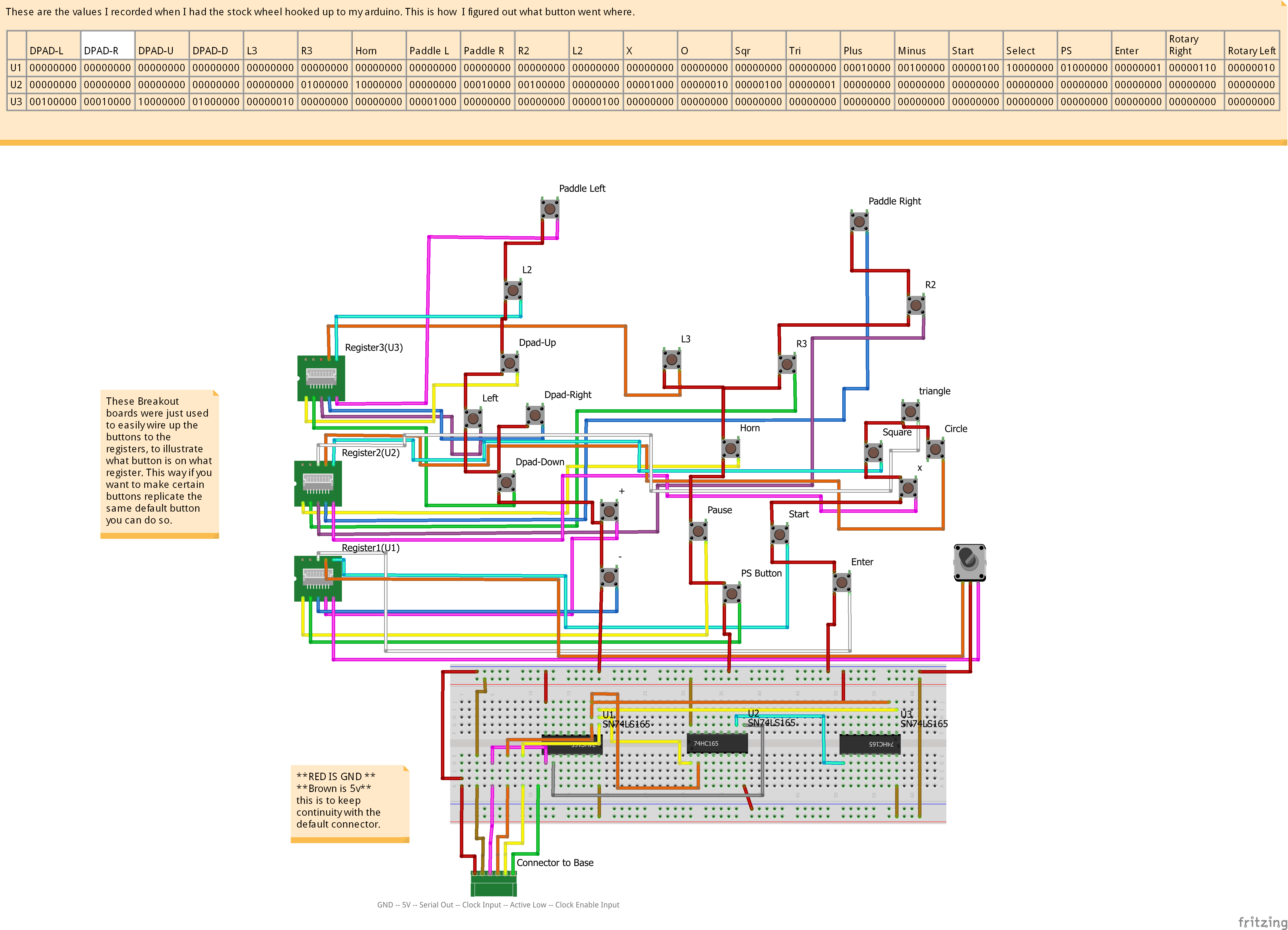
From here on all I did was push each button record which bit changed on which chip, and made a sketch of the connections. The only ones that confused me for a bit was the really cool rotary encoder( I have never seen one like it, I only have experience using the basic EC11 encoders.) But I knew it was changing one bit one way and another bit when rotated the other way, but sometimes while rotating the counter clockwise bit would flick on and off, and didn't seem consistent. At this point I remembered that using this before hand in games it wouldn't always register, so I believe the encoder is just missing turns, but I think you should be able to use these just as regular buttons as when you map it as is in games it registers as a button.
Output and Wiring of the buttons to chips
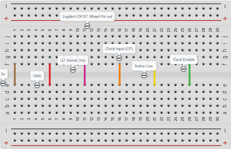
This is the pinout of the default cable that runs through the steering wheel.
This is the arduino sketch that I used to debug the stock wheel https://create.arduino.cc/editor/Bsc0n/e9f61a44-7c51-463f-b5b7-3314ecabc972/preview
The next step will be making a prototype pcb with some 74HC165 chips and buttons and seeing if the stock boards recognizes them or not. The chips are already on there way so I will update here when I either get it working or fry something :).