 Capt. Flatus O'Flaherty ☠
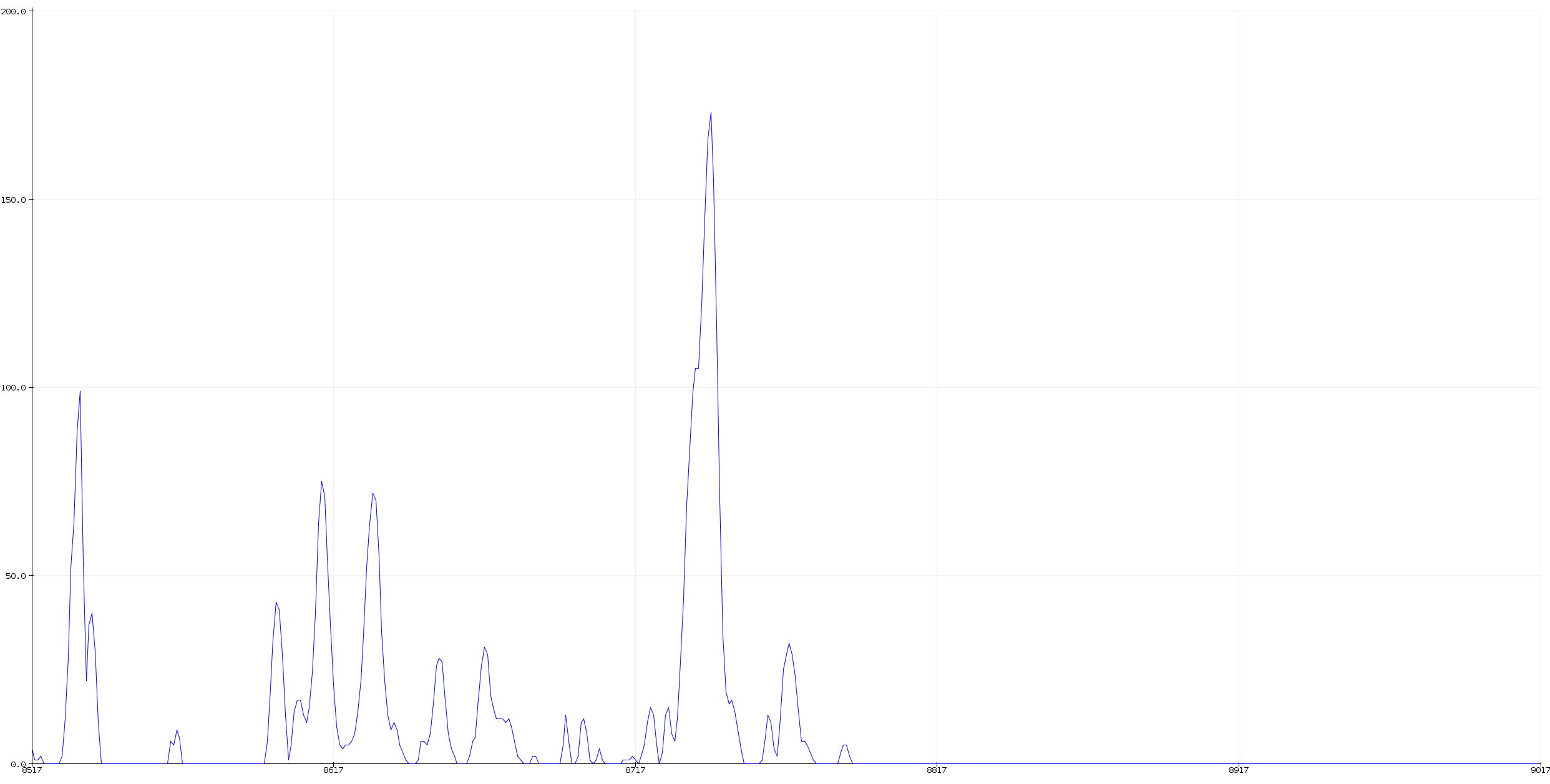
The Maxtronic sensor can detect multiple objects at the same time, as seen in the time line graph above. The peaks indicate the reflectivity and size of the object, so, for example, the peak shown in the middle of this graph could be either a small highly reflective metal object or a large absorbing object such as an animal. The screen-shot above is a representation of a cluttered room with multiple relective surfaces at different distances.
Fear not, for the mighty M4 processor can capture enough of this data and process it fast enough to get meaningful interpretations of these graphs. Fortunately, there is no Fourier Transform necessary as the data is already on the time line and we dont have to capture all the data either, just one out of every four bits of data needs to be captured, with three data points being skipped. This makes processing the data faster and easier to display using the Arduino IDE plot data function.
After the data is held in a large array, it is normalised by subtracting from some previously recorded calibration data, which removes the initial transmit spike and puts it all at zero on the Y axis.
The peaks are each identified by using a simple maximum value with the width of the peak being the length on the X axis of the data around it. Each peak, or spike, is then given an average X axis value and this corresponds to the distance away from the sensor. At the end of processing we end up with a load of spikes, each denoted by an ascending number eg 0,1,2,3,4 .... , the max value of the peak, the width of the spike and the distance from the sensor.
We can then select for spikes at a larger distance away from the sensor eg 8 m and filter out all the near-to-sensor data to prevent the LED display going off all the time and save the batteries.
The LED display is split up into 8 parts and each is controlled by a separate channel in the L293 motor driver chips. Each part can be dimmed by changing to ratio between on and off with a simple delayMicroseconds command. The Arduino PWM library could also be used. When used in the dark, the display needs to be substantially dimmed so as not to dazzle car drivers coming up from behind. In the daytime, the dimming can be removed entirely and the LED display is nicely visible, even in bright sunlight. The LEDs themselves are fairly up-market, super bright specs and not the cheap every day LEDs we might otherwise use. There are even better LEDs than the ones I used, but they start to get pretty expensive and the ones I have selected were a good compromise between cost and brightness. The L293 chips basically act as current amplifiers and allow more than 50 LEDs to be controlled from each channel, which would otherwise destroy the Adafruit M4 Express board, releasing the 'Magick Smoke'. The L293s can also drive high intensity sound devices and produce quite a piercing tone at high frequency, which is useful for testing as otherwise we would never know if the LEDs were activated or not. A slider potentiometer is used to control the pulse width of the LED timer such that a longer ratio of digitalWrite HIGH to LOW gives a brighter display.
Discussions
Become a Hackaday.io Member
Create an account to leave a comment. Already have an account? Log In.