 Tim
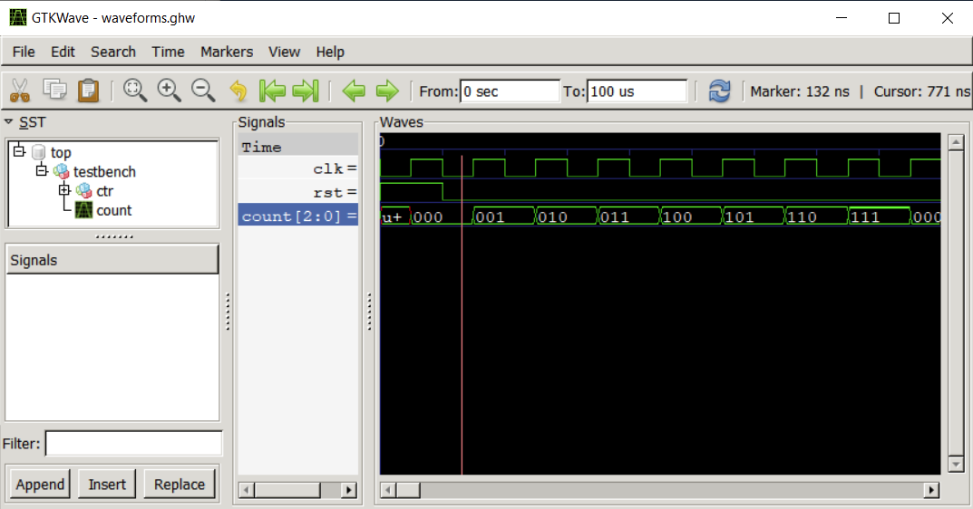
TimDigital simulation is quite straightforward. GHDL is well established here. I implemented a simple counter in VHDL to use an example for flow development. The source code is shown in the figure below and simulation traces from the testbench at the bottom of the page.
I implemented this part of the flow based on a standard Makefile. I switched to normal bash scripts for later parts because it became difficult to track built dependencies across folders. I may have to look into Tcl/Tk or other solutions at some point.
entity counterx is
    port (clk:  in  std_logic;
          rst:  in  std_logic;
          count: out std_logic_vector(2 downto 0)
    );
end;

architecture main of counterx is
    signal  cnt:    unsigned(2 downto 0);
begin

    process (clk,rst)
    begin
        if rising_edge(clk) then
            if (rst = '1') then
                cnt <= (others => '0');
            else
                cnt <= cnt + 1;
            end if;
         end if;
    end process;

    count <= std_logic_vector(cnt);
end;
Discussions
Become a Hackaday.io Member
Create an account to leave a comment. Already have an account? Log In.