 John Opsahl
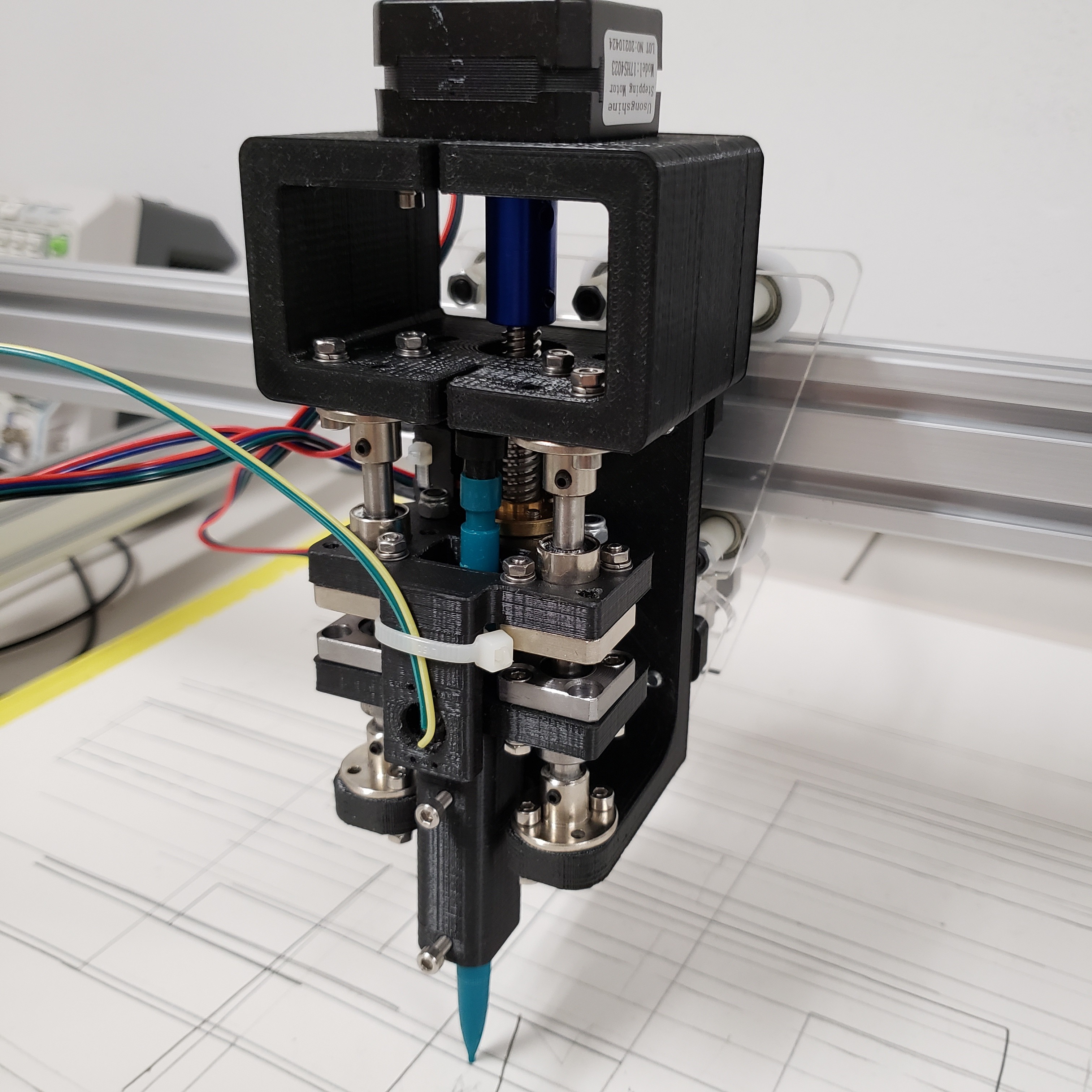
It took three attempts but I believe I have arrived at a viable method to control the amount of force between the pencil graphite and paper. This third approach uses a slide potentiometer and two springs. The springs are placed between the driver cart (the cart directly connected to z-axis motor lead screw) and driven cart (the cart with the pencil that floats freely on the z-axis). As the driver cart moves down, the pencil graphite contacts the paper and begins to compress the springs between the driver and driven carts. All the while, the slide potentiometer is used to measure the relative vertical distance between the driver and driven carts (i.e. the spring compression distance).
By Hooke's law, we know that the amount of force needed to compress a spring is directly proportional to the distance that the spring is compressed => F=kx. More spring compression distance -> more force. Less spring compression distance -> less force. Therefore, a control on the slide potentiometer readings will allow control of the force between the pencil graphite and paper.
My initial approach to spring constant selection has been the following. At full compression, the spring force must be near but no greater than the holding friction force between the graphite and mechanical pencil. When the force between the graphite and paper exceeds the holding friction force between the graphite and mechanical pencil, the graphite "slips" and is pushed back into the mechanical pencil. Having a spring force that is near holding friction force results in a wide range of graphite to paper contact forces (i.e. a wide range of light to dark pencil markings).
I anticipate that there is a point at which increasing force between the graphite and paper will not result in result in darker markings. Instead, the graphite will start to deform or tear the paper. Consequently, a more practical upper limit on the spring force at full compression is probably when the darkest pencil marking is achieved without deforming the paper. The main benefit of a lower upper limit of spring force at full compression is better slide potentiometer resolution -> a larger displacement (i.e. change in resistance) results in smaller change in contact pressure. My plan is to eventually make spring selections based on this approach, but the method described in the paragraph above is easier to determine and good enough for now.
The main challenge I am working against right now is friction between the z-axis bearings and rails. The friction between these components prevents achieving low contact forces between the graphite and paper. It is bad enough that the current design cannot achieve what could be considered as light pencil markings. I believe the issue is that the 3d printed design is not square enough to achieve good alignment between the bearings and rails; the bearings are binding up on the rails. Two approaches that I have considered to resolve this: 1) redesign 3D printed parts to include rail and bearing adjustment features, 2) redesign the assembly for laser cut that has better part tolerance. Redesigning for laser cut is going to be the simplest and probably most successful approach. Primarily because I am very familiar with using laser cut parts for cnc design and laser cut has much faster turnaround time if I mess something up.
Discussions
Become a Hackaday.io Member
Create an account to leave a comment. Already have an account? Log In.
Are you worried about spring deformation? I'm not sure that's the right terminology, but as the spring goes through compression and decompression cycles, the amount of force required for compress it goes down, doesn't it?
Are you sure? yes | no