So I went back to the dollar store for an unrelated purchase after printing my 3rd version of the center magnet box. I popped over to the stationary aisle just to see if anything had changed in my favor, and indeed it had. They had a nice fat stack of mini magnets. These are 3mmx6mm and quite strong for their size at 280 milliteslas (compared to 240 for the larger ones, umm ok). A dollar buys 8 of them, so enough to make 2 boxes with 2 IO each. Half a dollar for a box is approaching (if not slightly past) my ideal cost, but since everything else is super cheap, I haven't felt the need to source cheaper alternatives online.
Using these magnets was my original idea, so I decided to quickly change the design to incorporate these magnets instead of the slightly larger ones. Since I tried to make things as modular as possible in my .scad file, it worked out very quickly. I wanted more pulling power, so I put 2 magnets per side, and I changed the design to use a centrally located electrical connection to simplify everything and equally distribute forces. The main issue I was running into with the offset screw connectors was that they tended to get bunched up in the corners when building L shaped pieces (see the previous image of the v1 box). Centering the connector made each side equally in and out of the way of the other sides. I didn't want to make these boxes very big (relatively speaking), so things are a little cramped by design. Of course I also didn't want to make everything too small, or children would have trouble manipulating the pieces.
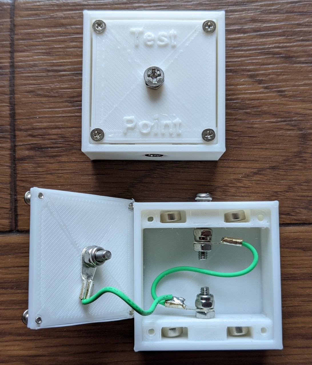
Here is an example of the inside and outside of a simple v2 pass-through box. The lid on this box is a "Test Point" lid, so it's purpose is to allow us to tap into the circuit at any point and test the integrity/characteristics of the circuit easily with a multimeter or oscilloscope. The keen observer will notice a few differences between the hardware on the boxes as well as the hardware on the different connectors within the same box. I'll address these points later. The S shape of the wire between the 2 sides seems to be the ideal shape for the wire to allow the spring loaded screw to depress without becoming jammed by the threads on the screw. Clearly a smooth shafted part would work better here, but we're dealing with DIY prototypes. It'll be ok.
More to come soon. The next chapter will be about all about my design decisions of the various boxes and lids.
Discussions
Become a Hackaday.io Member
Create an account to leave a comment. Already have an account? Log In.