So I'll be honest the beginnings of this project were very much inspired by this recent HAD project post https://hackaday.com/2021/07/14/analog-style-vu-meter-with-arduino-and-oled-display/
This is why I love HAD, coming up with creative original ideas is very difficult with the saturated diy maker world but seeing what other people are doing is a great source of inspiration to starting similar projects with improvements sparked by the lessons learned by past projects others have done!
So while what I've implemented is certainly not unique, it's interesting to me nonetheless. From the original project I referenced above I saw two main issues I'd like to resolve. The first is each display required it's own arduino to drive it, one for the left channel and one for the right one. I've implemented my own bitbanged spi oled driver code in the past, so it was simple to update it to support two displays each with their own chip select pin, but sharing the rest of the control pins. This meant one chip could drive two displays, sequentially. My bitbang spi code uses direct port manipulation, and can refresh one screen at just above 40Hz (so logically dividing the communication bandwidth between 2 displays will mean each display can updated at around 20Hz max each). It'd be trivial to change the code to support hardware spi which would greatly further increase speed, but I don't think that's necessary at the moment.
The second issue I seek to improve is that the meter movement in the original project looked a little too perfect and instantaneous, as you'd expect with a digital display. If you've ever seen a mechanical meter movement it's apparent that the mass of the needle and the spring that is attached to it to return it to zero when no signal is driving it add a physical response to impulses. The needle will take a little while to accelerate/decelerate, often overshoot the setpoint a little, and slightly oscillate around the point till it reaches equilibrium. This is the exact behavior I want to approximate with my virtual needle on a digital oled display.
To accomplish this I've implemented a PI controller (basically a PID controller without the differential term). Conventionally such a controller is used to smooth out physical responses so an output can reach a setpoint as quickly as possible without ringing or overshoot, but I'm ironically adding it to add those desirable features for this application lol, by purposely selecting gains which result in underdamping. Here's a snippet of code to demonstrate generally how the PI controller is implemented:
//these gains affect rise/fall time, overshoot, oscillations
double p_gain=0.2;  //proportional gain
double i_gain=0.8; //integral gain

val=analogRead(A0)/8; //val is the measured setpoint/reference, divided by 8 because the adc is 10 bits but the meter range I've chosen is only 7 bits

err=val-pos; //the error is how far off we are from the setpoint, pos is the current needle position

err_accum+=i_gain*err; //here we calculate the scaled factor of how long there's been an error

pos+=(int) (p_gain*err+err_accum); //we add the accumulated error with the current error scaled by the proportional gain to calculate what the next position should be
// The position must be an integer from 0-127 so we cast the calculated value from double to int

if(pos>127) pos=127; //these are limiters to make sure the output never exceeds the max or min deflection of the needle
if(pos<0) pos=0;
As you can see, if the setpoint is much larger than the current needle position the error will be large and the correction applied to the next position will be large as well. And if the error has been non-zero for quite awhile, the accumulated error term will be large, further increasing the corrective action. Notice also that these terms can be positive or negative in order to force the corrective action in either direction to keep acting until the needle position and setpoint are the same (thus error=0, so long as there's no steady state error). Depending on the values of the p,i gains you can tweak how fast the needle moves, how much overshoot there is, how much ringing, etc.
So the big question is how did I calculate the ideal values for these gains ... I guessed and iteratively tuned them till they looked right! I attached a potentiometer to the analog input and by tweaking values while I twiddled the knob I could see the physical response of the needle to step impulses. I know that feels cheap compared to calculating the correct values by modeling the differential equation for a mass spring system and then solving for the gains of a PID compensator given that plant model, but it was certainly quicker and it looks fantastic. Sometimes you just have to throw caution to the wind and do what works easily/quickly over the conventional method! Anyway, I'll soon post a video demonstrating the algorithm above running compared to no physics modeling and with different gain values, stay tuned (pun intended!).
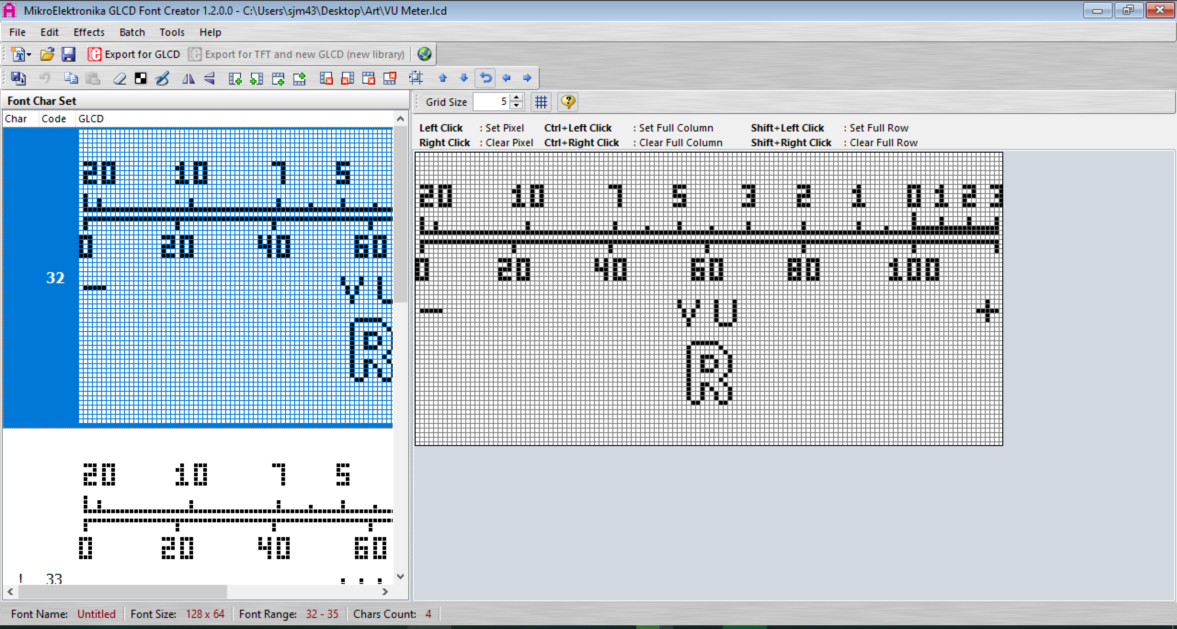
The background is just a bitmap stored in flash, which I drew in GLCD font creator.
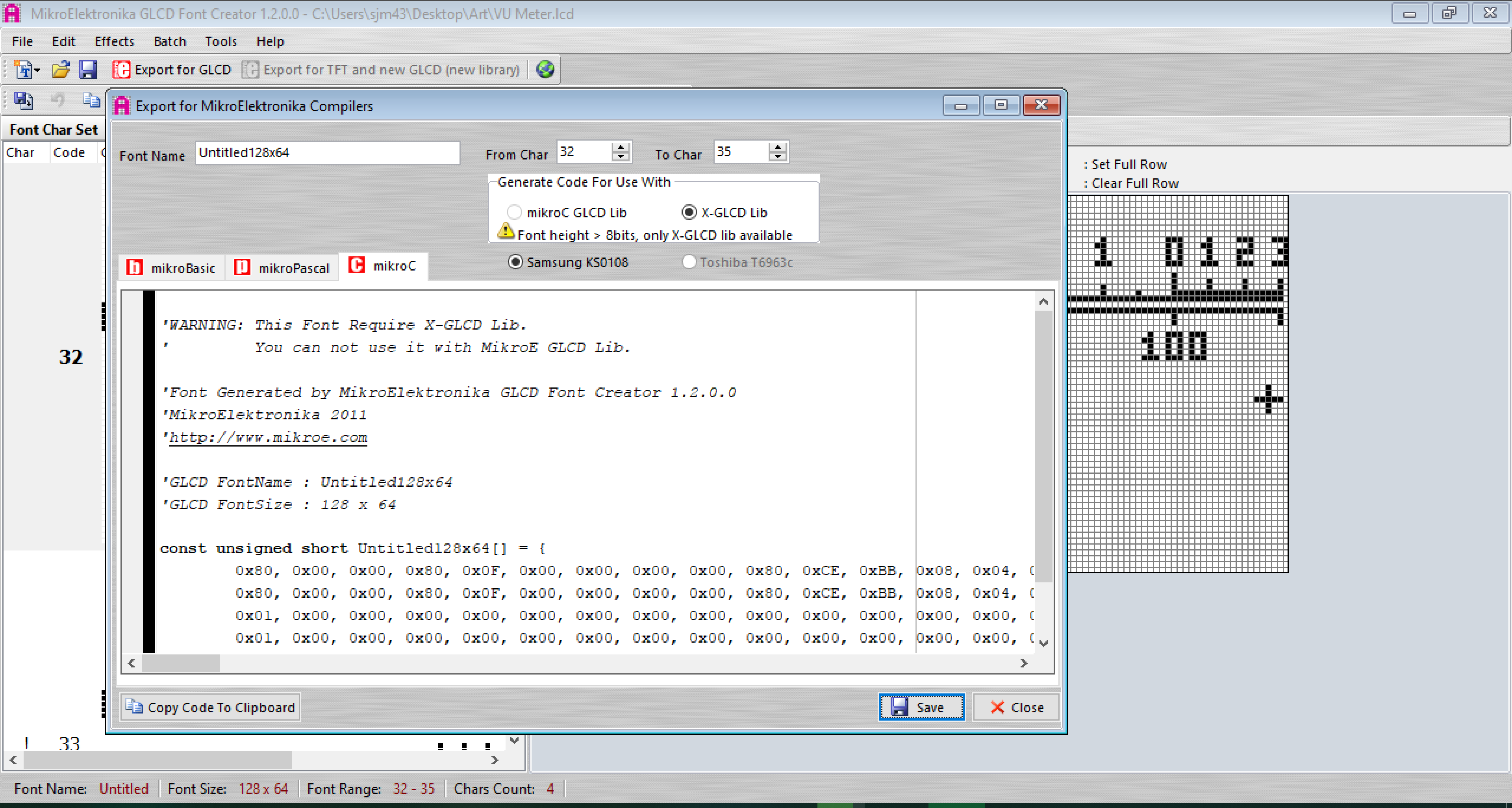
 Thanks to the built in array tool, I can just copy and paste the generated array output into my code (though I draw bitmaps a little differently in my code so I wrote an additional script to rearrange the array a bit to be compatible).
 It's loaded into a frame buffer and any other graphical elements like text can be overlaid easily before calling the draw function which blasts the buffer through spi to display on the oleds. To save RAM I only have one shared frame buffer between the two displays which must be overwritten with each new screen between writes.
The final piece of the puzzle is to draw the needle on the screen, wikipedia to the rescue!!! I found this entry (https://en.wikipedia.org/wiki/Bresenham's_line_algorithm) which describes Bresenham's line algorithm to draw a line of best fit between two given points that will fit a quantized matrix of pixels. I wont go into exactly how it works here, but luckily the article does a great job of that and most importantly provides pseudo-code which I used to write a function in C for the atmega. I did add a little flair by offsetting the ends of the needle on either end in arcs of different radii to make it look like how a real needle rotates.
 sjm4306
Discussions
Become a Hackaday.io Member
Create an account to leave a comment. Already have an account? Log In.
Looks very nice, please do post the code, and which LCD panel you are using!
Are you sure? yes | no
Will post code as soon as I'm finished! The display I am using is an SSD1309 128x64 OLED, it comes in 1.54" and 2.42" versions of a few different colors.
Are you sure? yes | no
Great , I will wait for code
Are you sure? yes | no