 shane.snipe
I had some basic questions that needed answering. Firstly, how linear is the sensor. Secondly, what is the optimum distance between the sensor and the reflector ramp.
For background, I am reading full scale 0-3.3V with 12 bit resolution or 4096 counts.
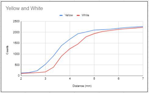
You can see for yellow, I have a roughly linear window from 2.66mm to 4.33. This is measured against a flat surface with cardstock as 0.33mm increments.
I am slightly embarrassed to admit took this data today, after working on the project for 9 months. When I started the project, I played with some different resistors but because the sensors were not mounted to anything it was hard to measure the distance accurately. i saw that the voltage changed a measurable amount with the resistor combination I chose and I moved forward to make some boards.
Angle measurement

Femur measurement

Unfortunately, my first design had the white PLA too close. I played with grayscale shading on paper and had good results so I tried grey. They reflectance was terrible there was almost no change. I then switch to yellow and saw much larger changes with angle but often on the last half of the rotation. I reduced the slope of the ramp and made it a bit further away and got good results. Here is a graph showing the counts versus angles for these 4 versions.
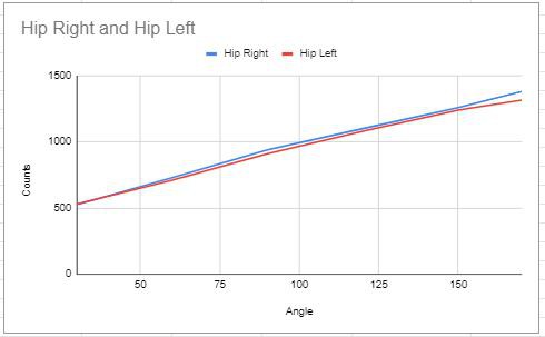
After seeing the good response on this profile reprinted the ramp for the to the hip joint and got this response.
Now if the other axis was similar, I could call it a day but I am getting some weird responses.
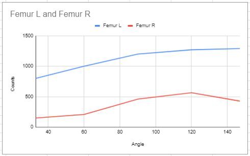
There are 5 things that are different with this axis.
1) The reflective wall is printed vertically so it does not change in defined steps like the horizontal surfaces. The horizontal surfaces look like a staircase because of the layer thickness of a print which actually work quite well.
2) There is support printed in the channel and remnants may be causing strange reflections.
3) The outer wall is so thin, it looks darker from the inside as you can see the tape on the outside.
4) The outer wall is thinner than the other two parts.
5) It is made of 2 parts so there is a seam that lets light in and it reflects differently.
Looking at it more deeply, I have noticed there is a large axial play in the shaft. This axis is not trapped very tightly. This was because it was trapped tightly and I had to almost deflect the hip to put it on. I reduced the model by a mm off the adapter on each side and now there 1-2mm of play. Looking up the page at the first graph we know that we only are working with 1.67mm of liner range and being two close does not do us any favors. By shifting the shaft back and forth axially, I can change the output by 500 ticks. No wonder I had such a hard time to measure it. When I measured the left, it was biased away from the sensor, when I measured the right, it was biased toward the sensor, reducing the gap.
I also see the sensor board is on an angle due to proud solder joints. This also makes it hit the side of the wall instead of the back and bouncing off. Combine that with a little support and that might explain why the end is wonky.
I will make the shaft adapters taller again so that it is line to line. The new boards with sit flat so proud solder joints will not be a problem. I will make the part 1.5mm thicker and push out the ramp by 0.5mm. The response does not have to be completely linear but it has to be continuous. If the slope change to negative my control algorithms will not work.
Too much play

Hip joint

Part progression

Discussions
Become a Hackaday.io Member
Create an account to leave a comment. Already have an account? Log In.