 shane.snipe
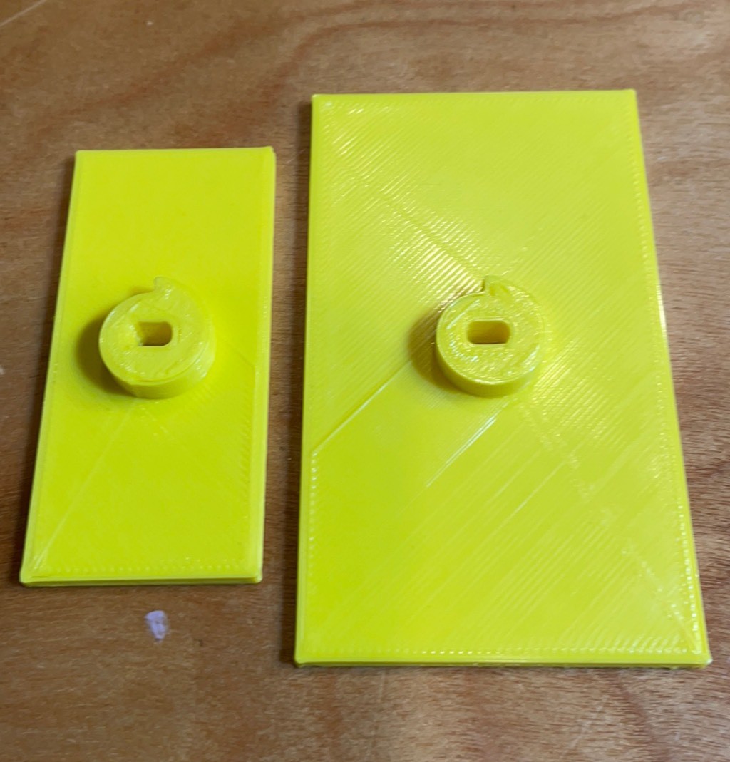
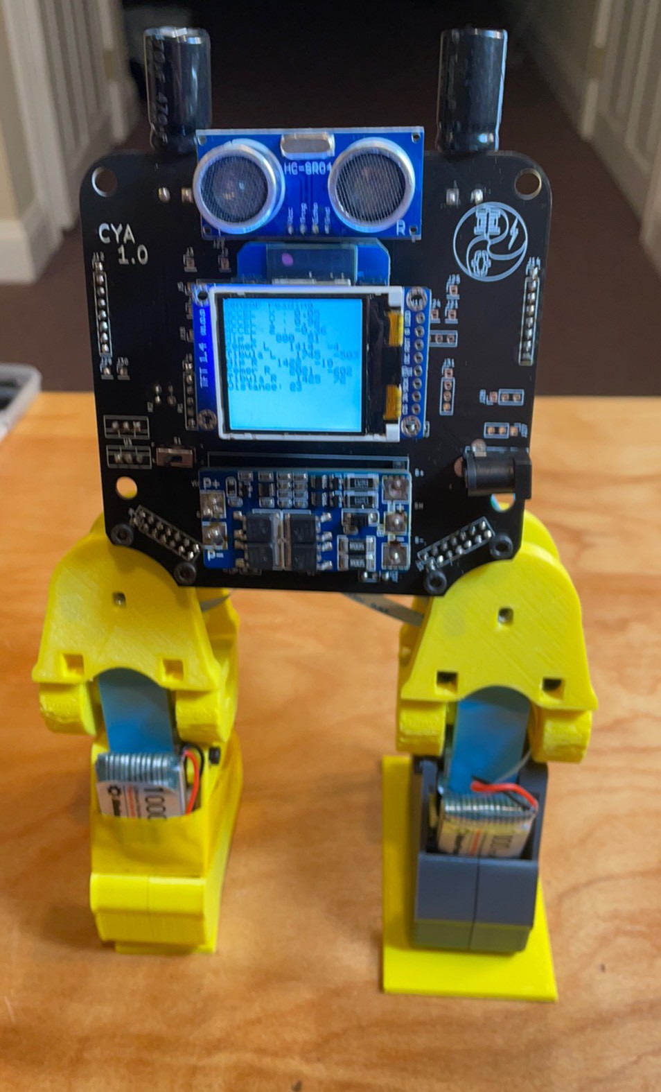
I had designed the original legs for Cya to mimic the joints needed for a quadruped. It needs the 4 legs to be able to turn. They also were a little too tall which made it a little more difficult to balance. So to allow Cya to turn on a dime and show off the unique advantages of continue rotation servos, I designed a rotational stage on the soles of the feet. The Onshape model can be found here.
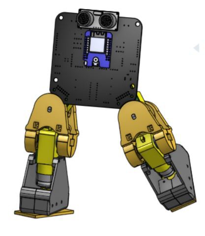
The foot can stay flat on the ground and if one leg is lifted, Cya can pirouette. Continuously. Like a roundhouse kick. Next goal, build it up and get a video of the pirouette. After than my next adventure will be working in Micropython.
Here are some assembly pictures for posterity.
Ready
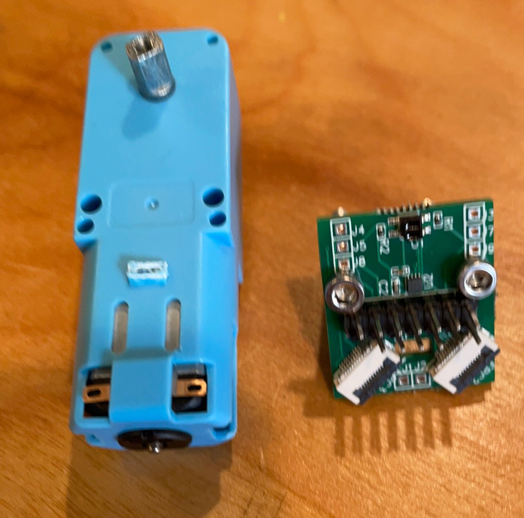
Bat positive
Battery negative
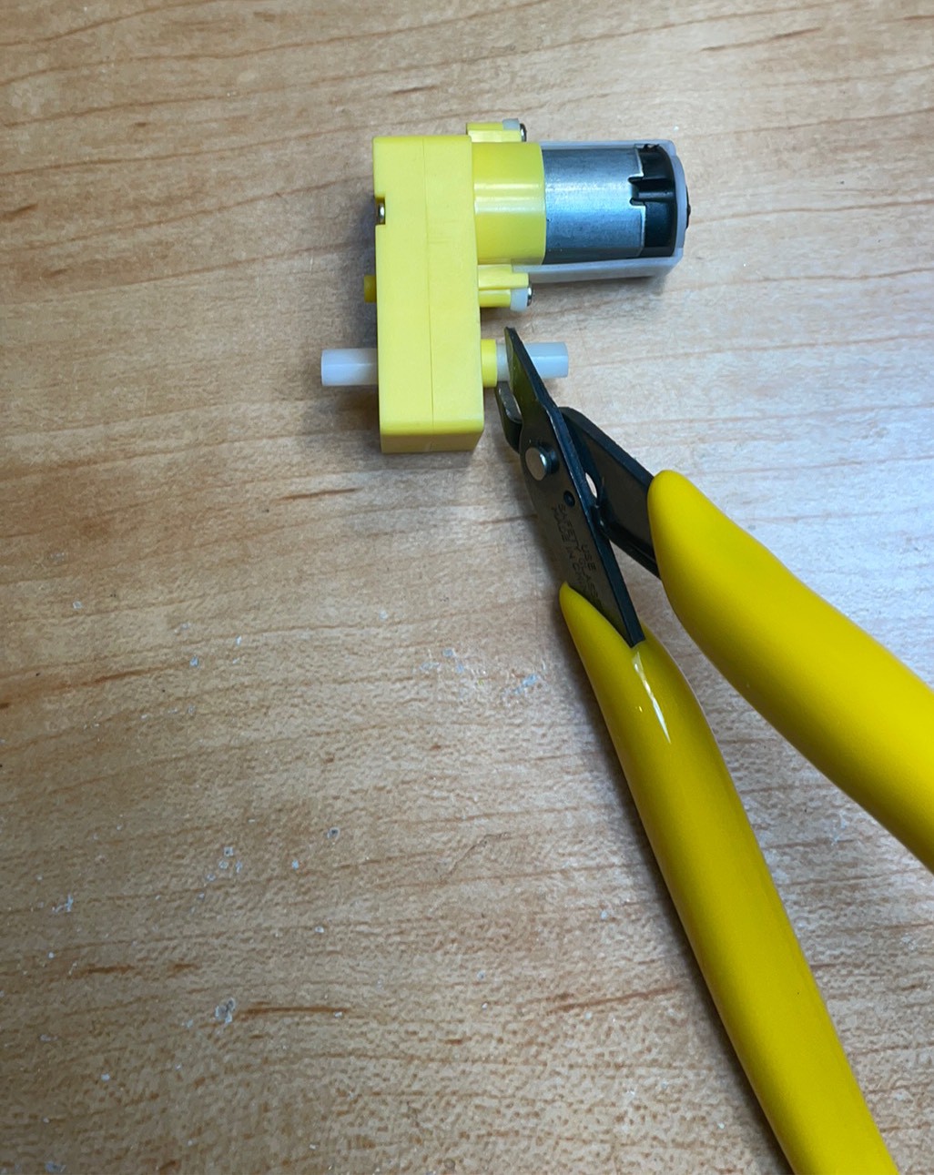
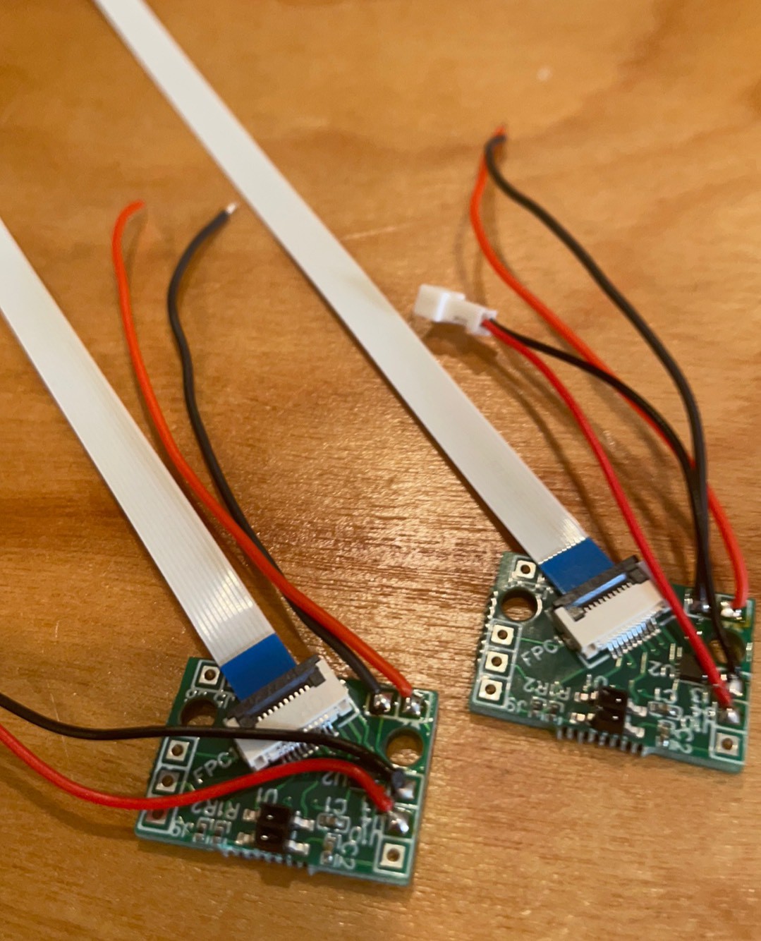
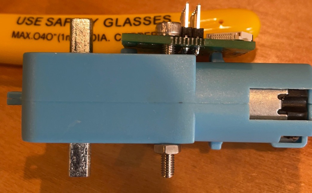
Cut off top shaft.
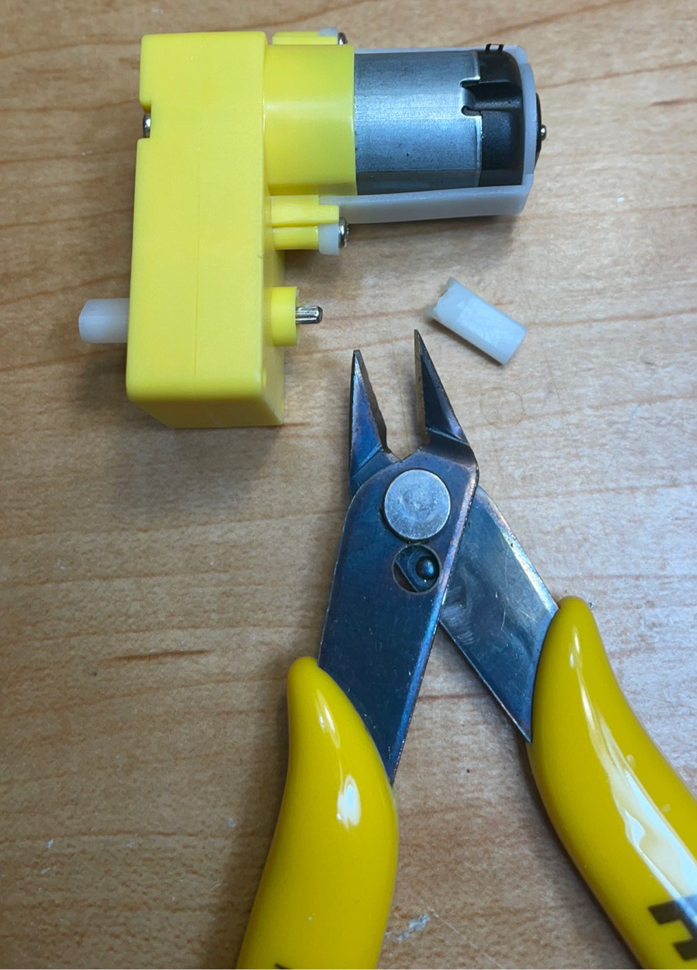
Cut complete
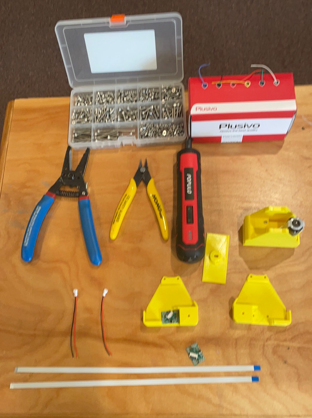
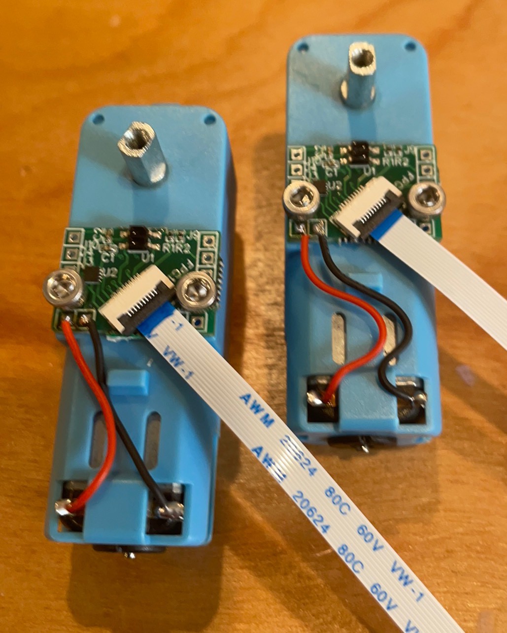
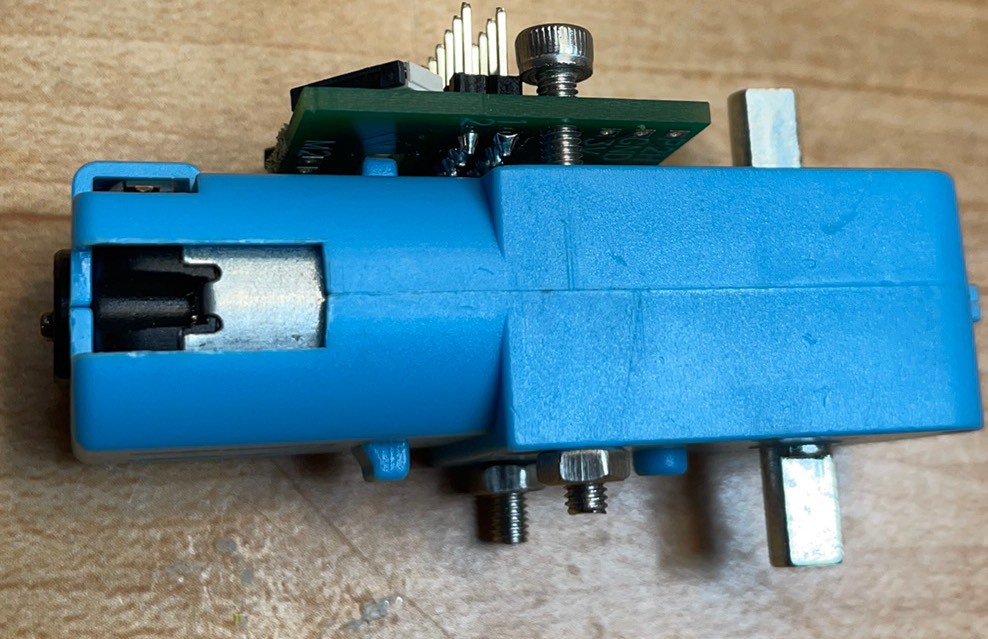
Solder on motor wires from the top to keep the back flat.
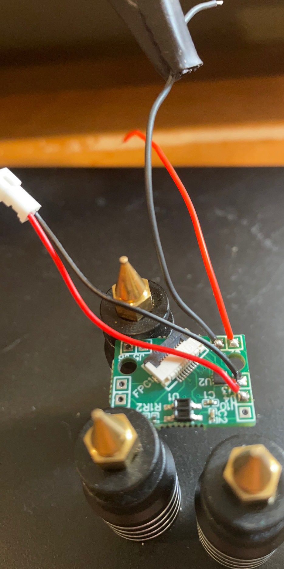
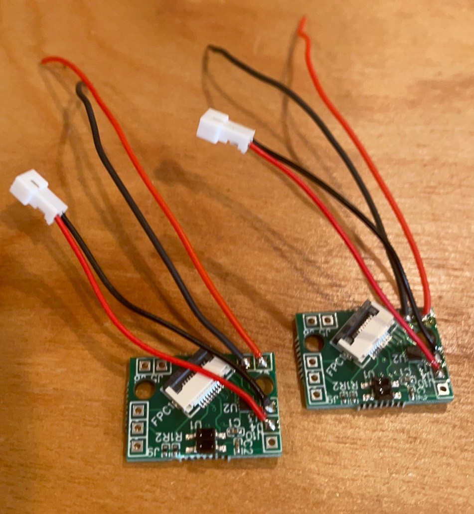
Front of boards done. Turn boards over to remove the excess solder to allow it to sit flat.
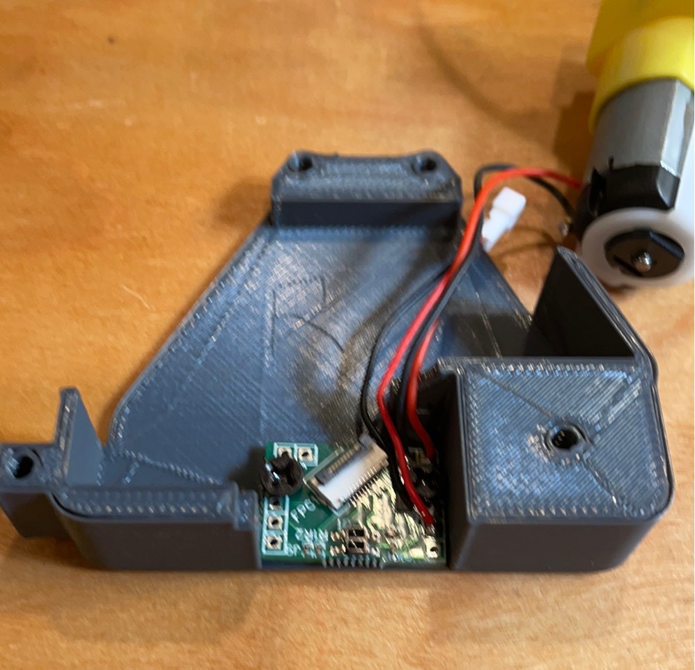
Insert cables blue side up, terminals down. Trying 25 cm. 20 cm works but is a little tight.
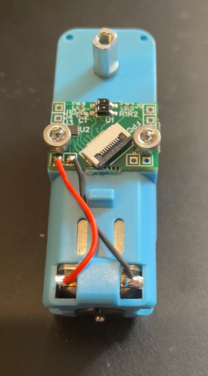
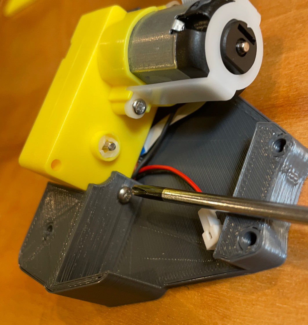
3x4mm flat head screws into the housing.
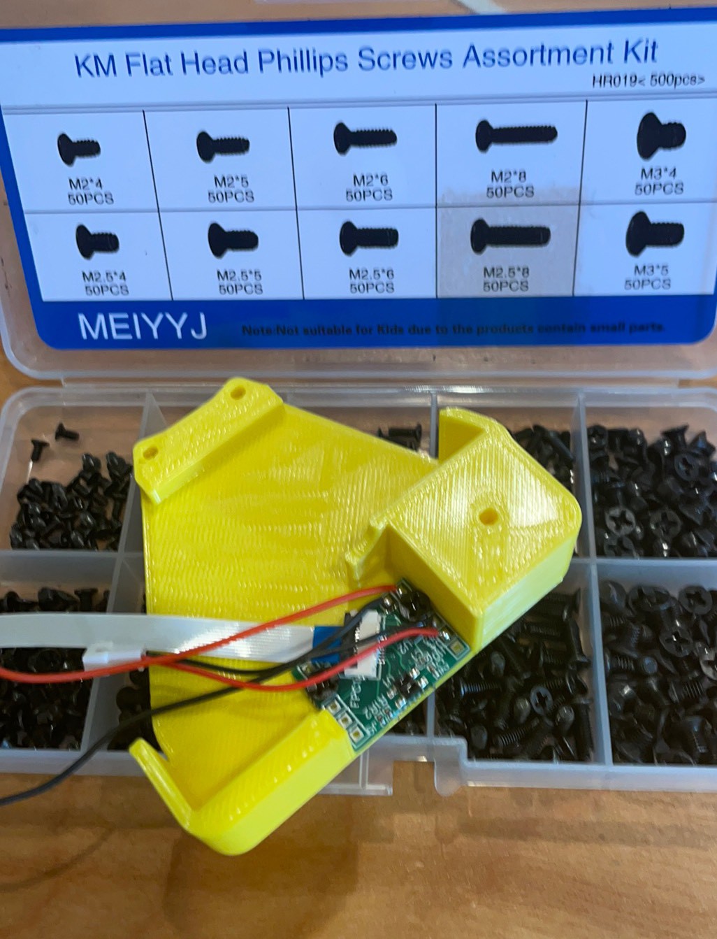
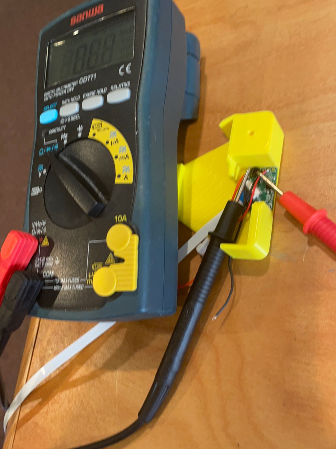
Check to make sure screw does not short To bat neg or motor positive or worse both! Use a washer if it does and a longer screw.
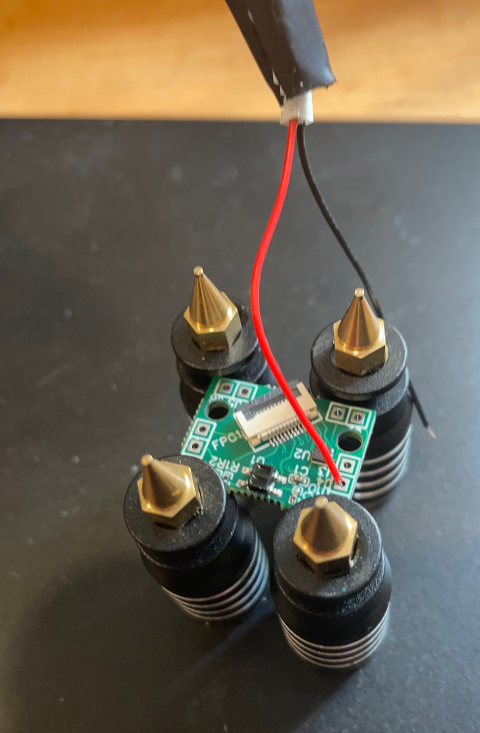
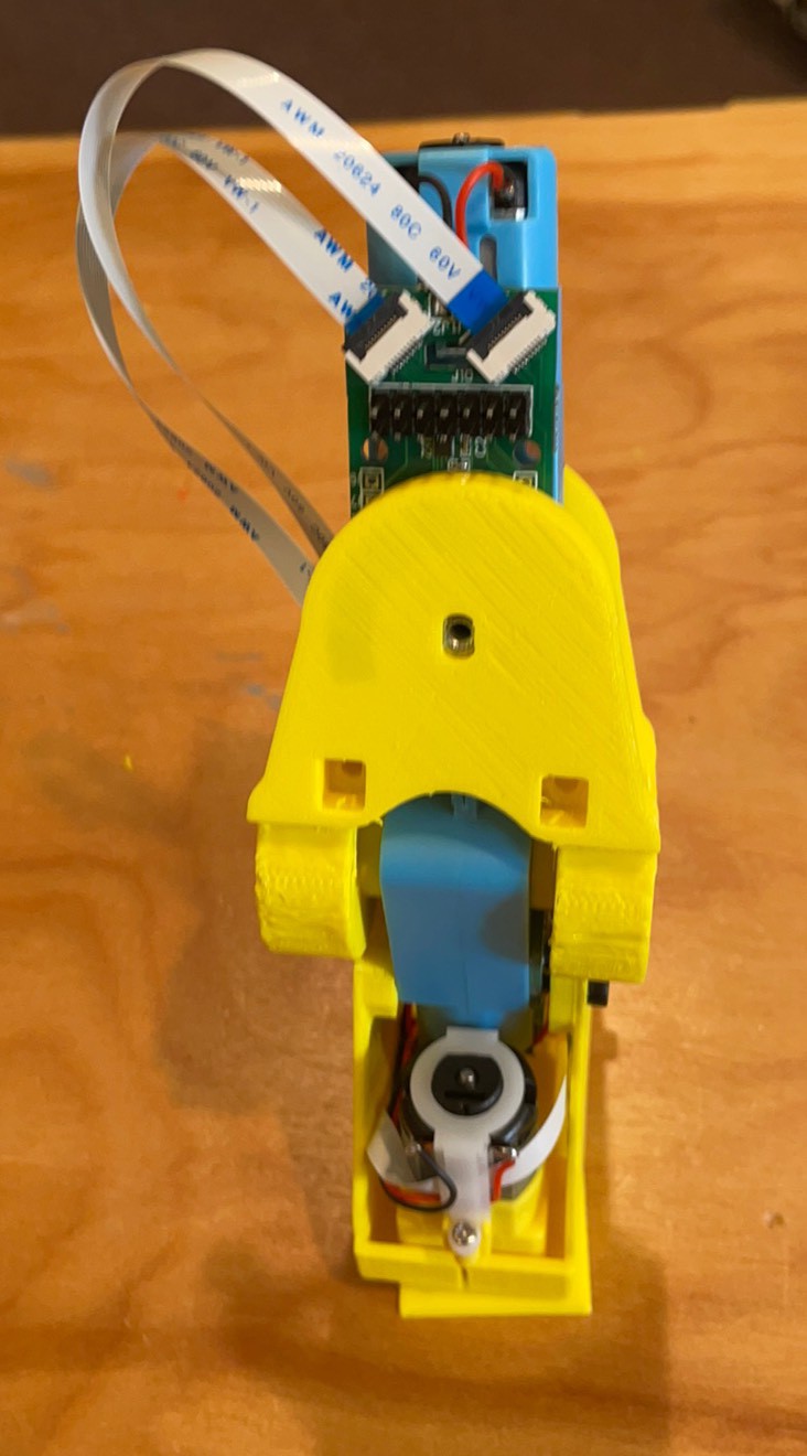
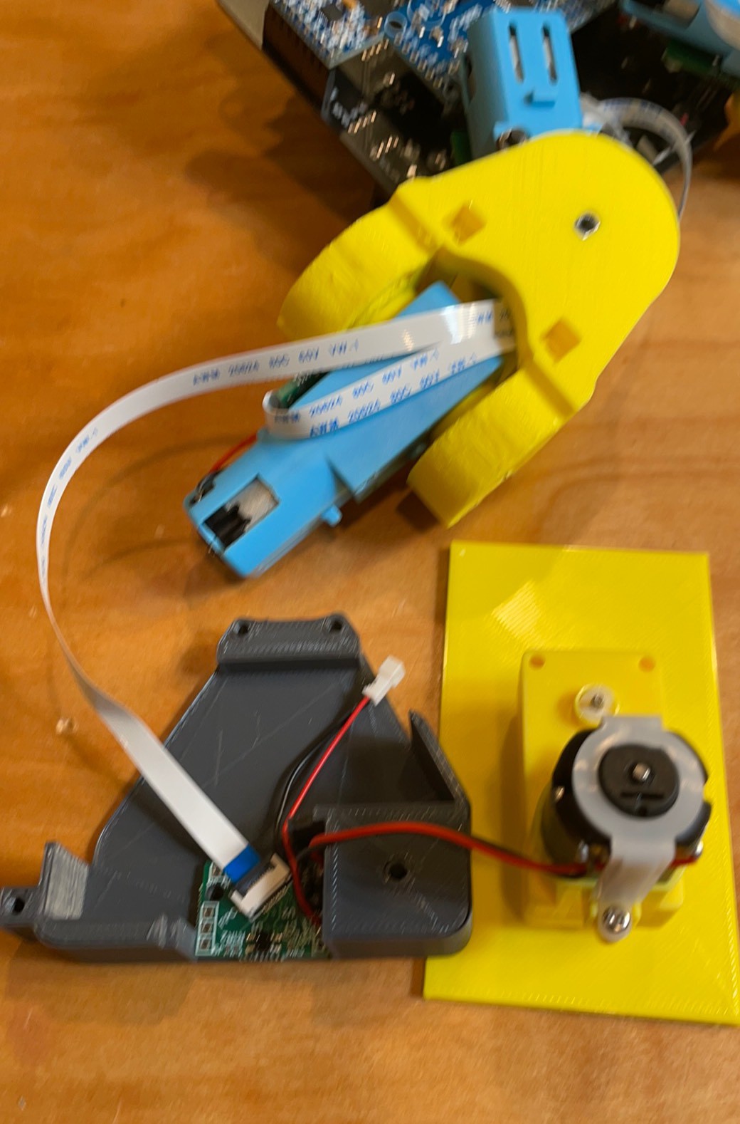
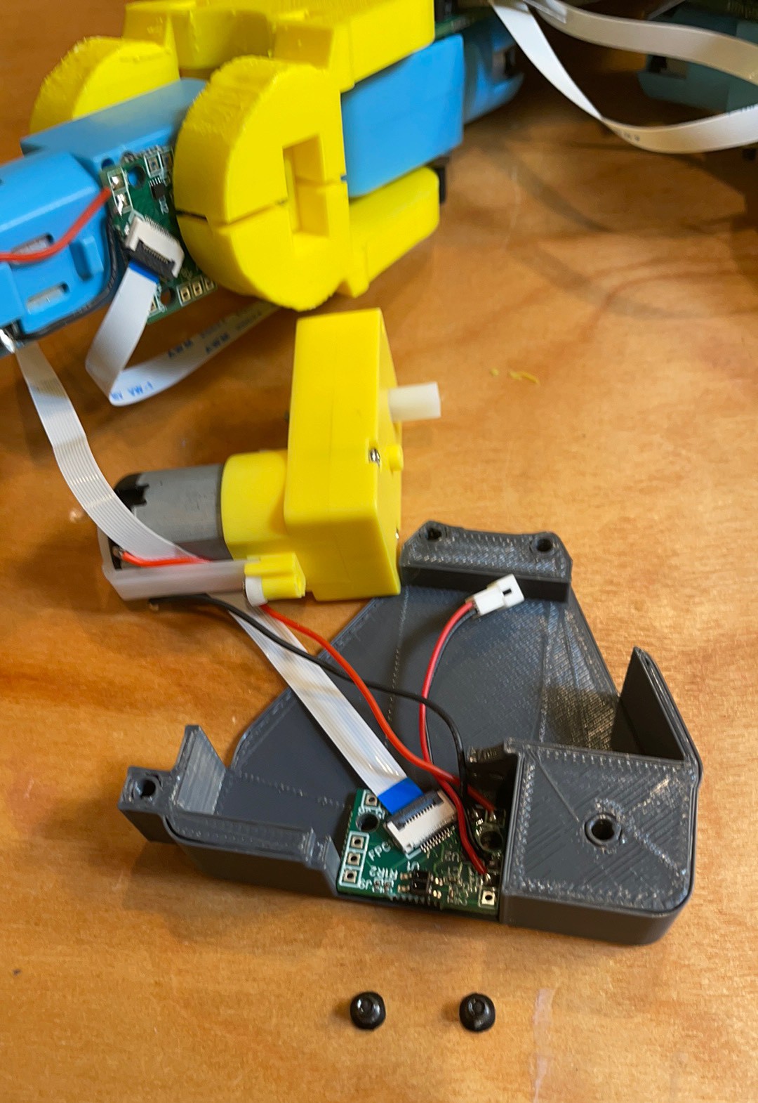
Route wires beside the FFC connector. It is line to line with the foot housing so wires above it will be squished.
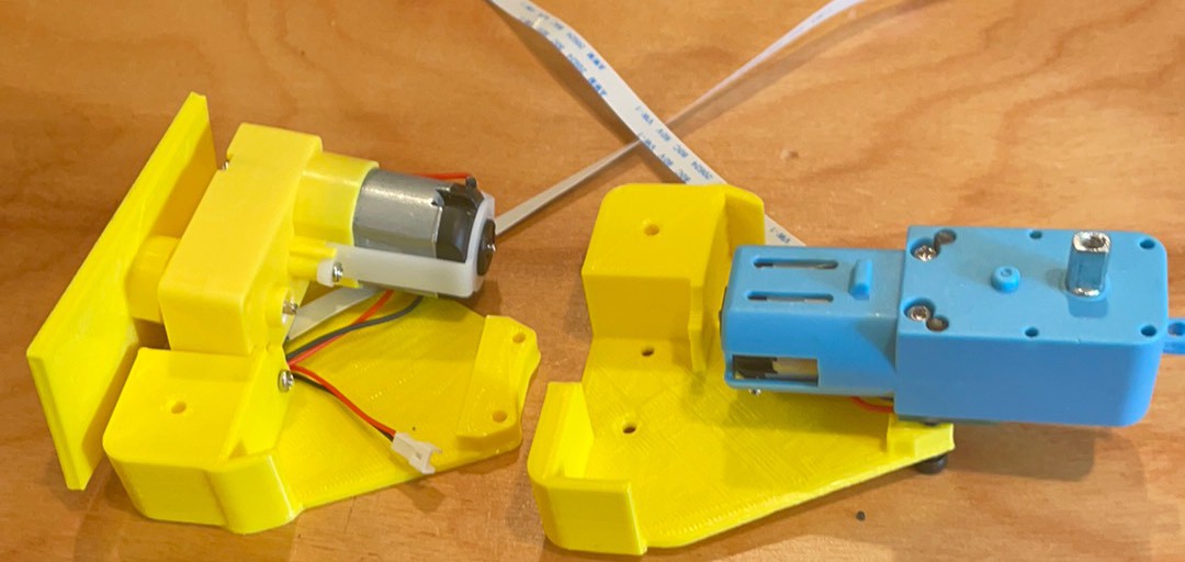
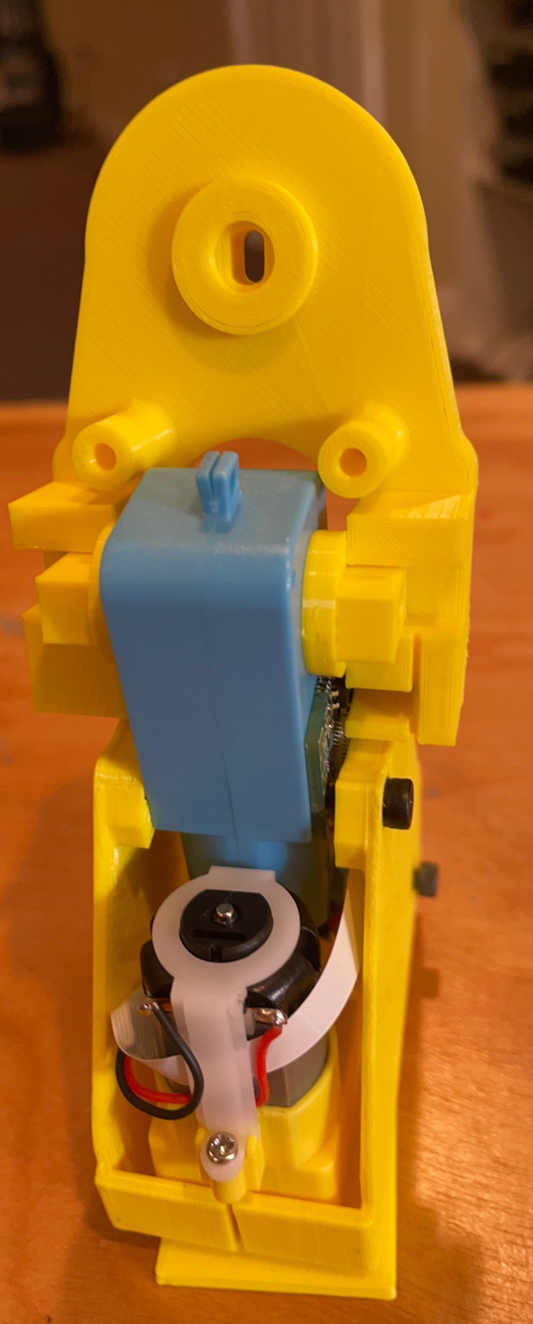
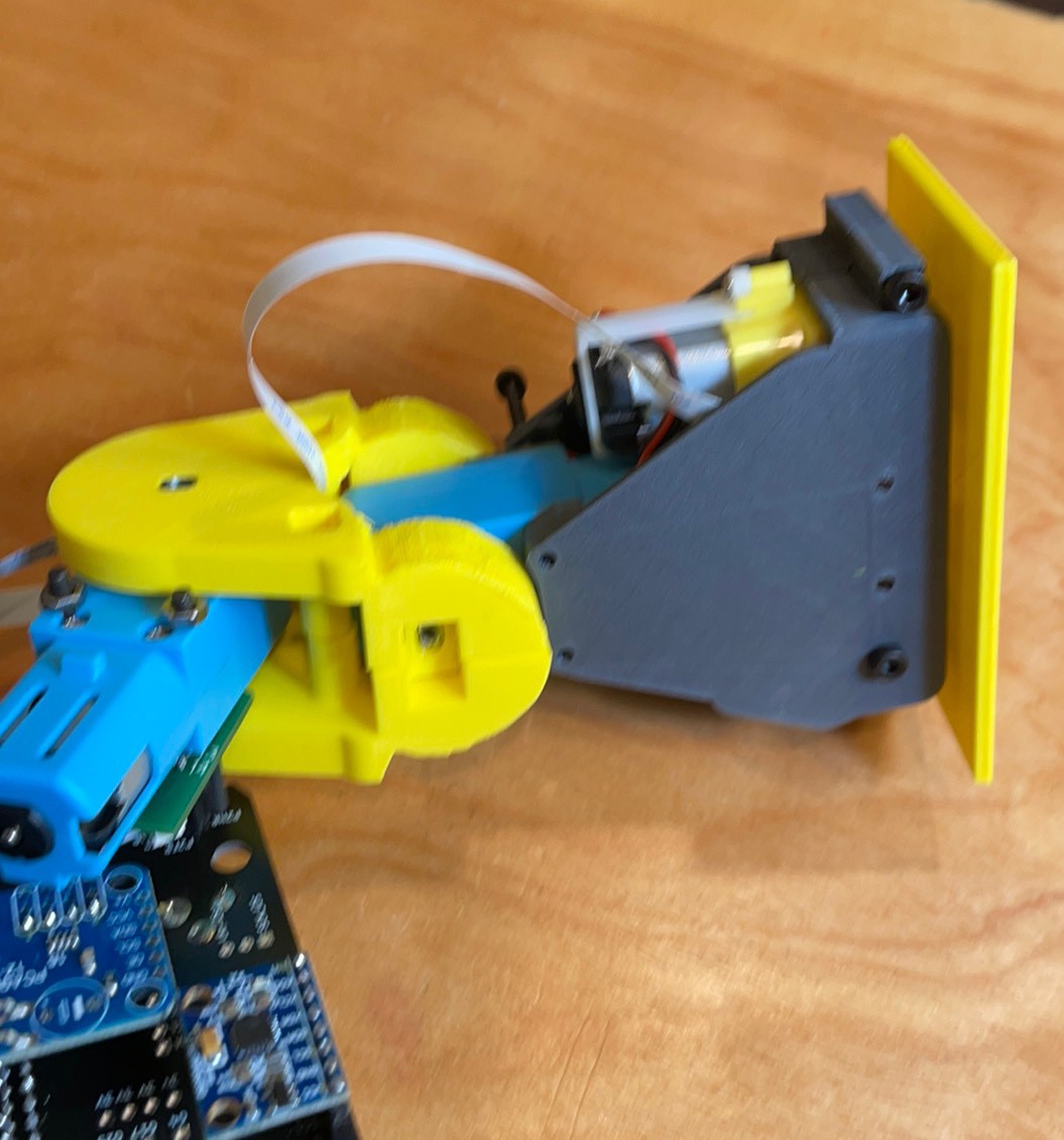
With and without the foot. Motor sits on the FFC connector and shaft boss is cradled buy the90 degree cut out.
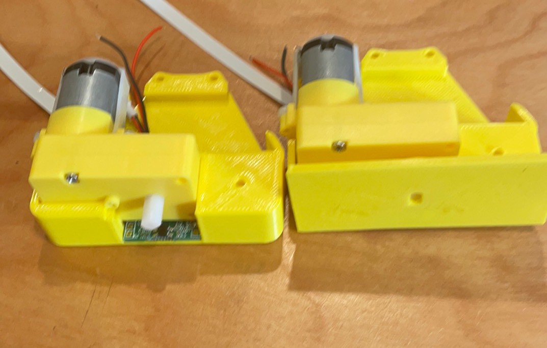
Was designed for the shaft to be flush with the bottom but if they are even and the foot is secure it might be ok. If it is not pressed on enough the sensor will miss the reflector. Too tight and it will rub. This is a point for optimization. Fit is an elephant foot issue.
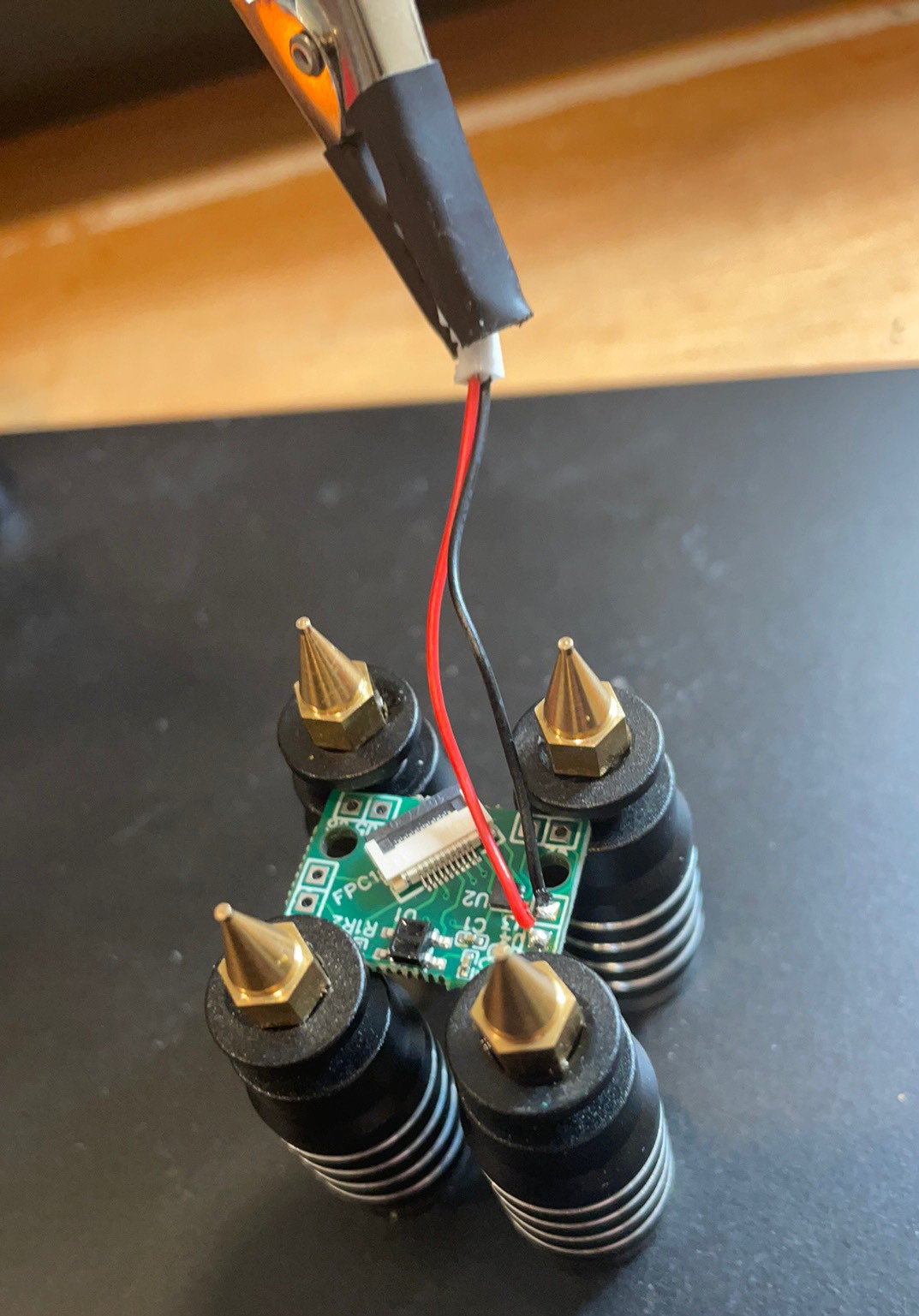
Put in the somewhat optional 2 mm screw in top of gearbox.
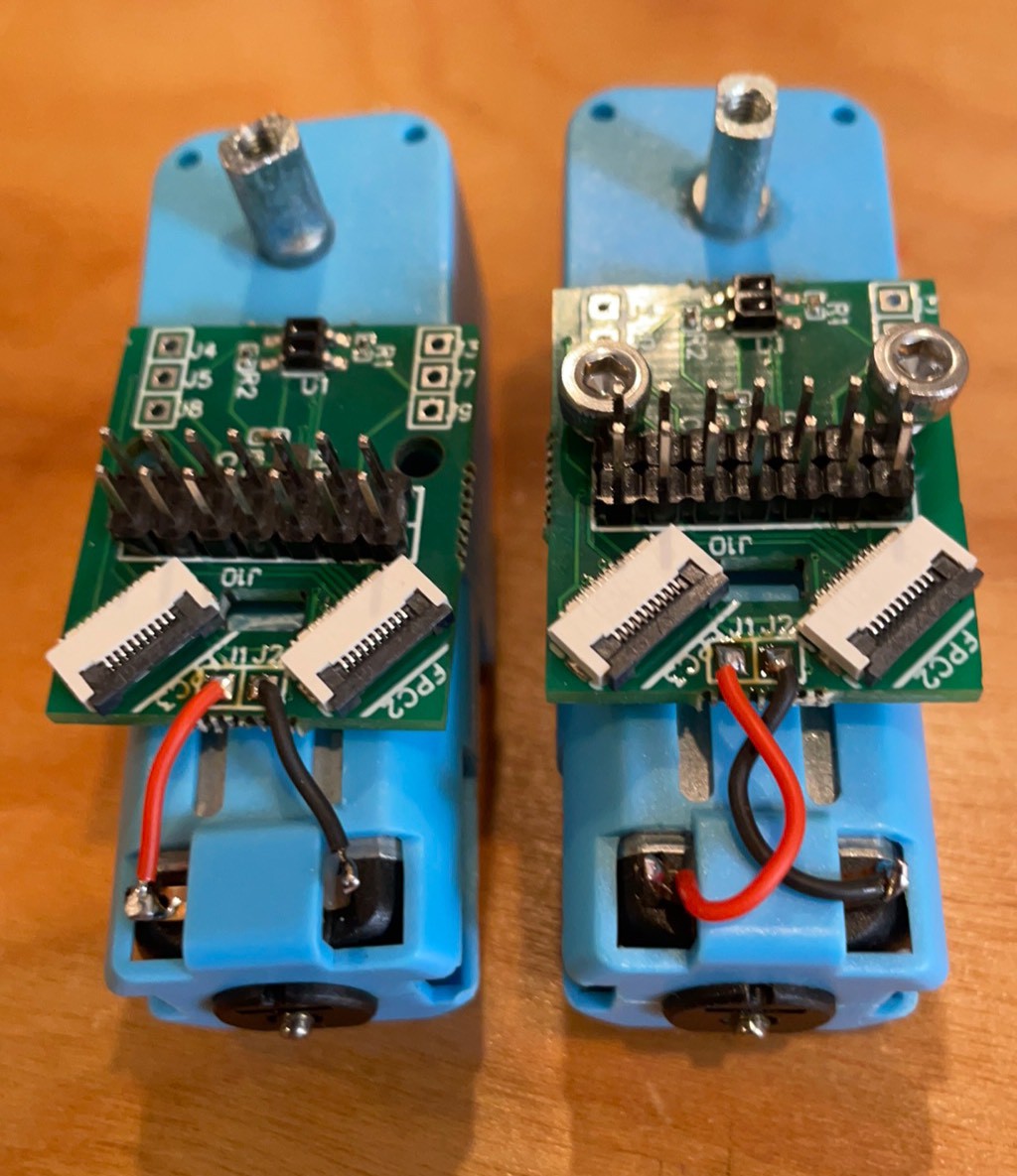
Black does the reaching here. Polarity is arbitrary until you try to use someone else’s code. Let’s standardize!
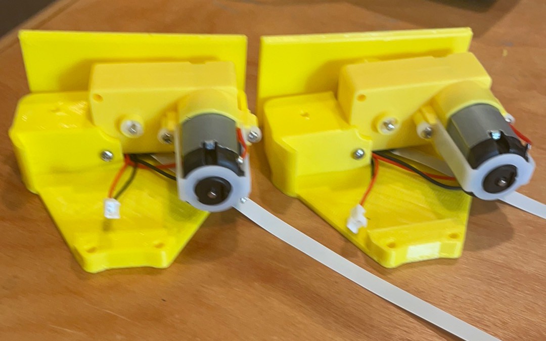
With 20 cm FFC and motor wires connected. Screws were just to hold it to solder.
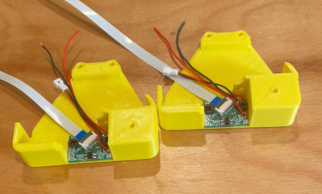
Assemble motor board and screws to other ankle.
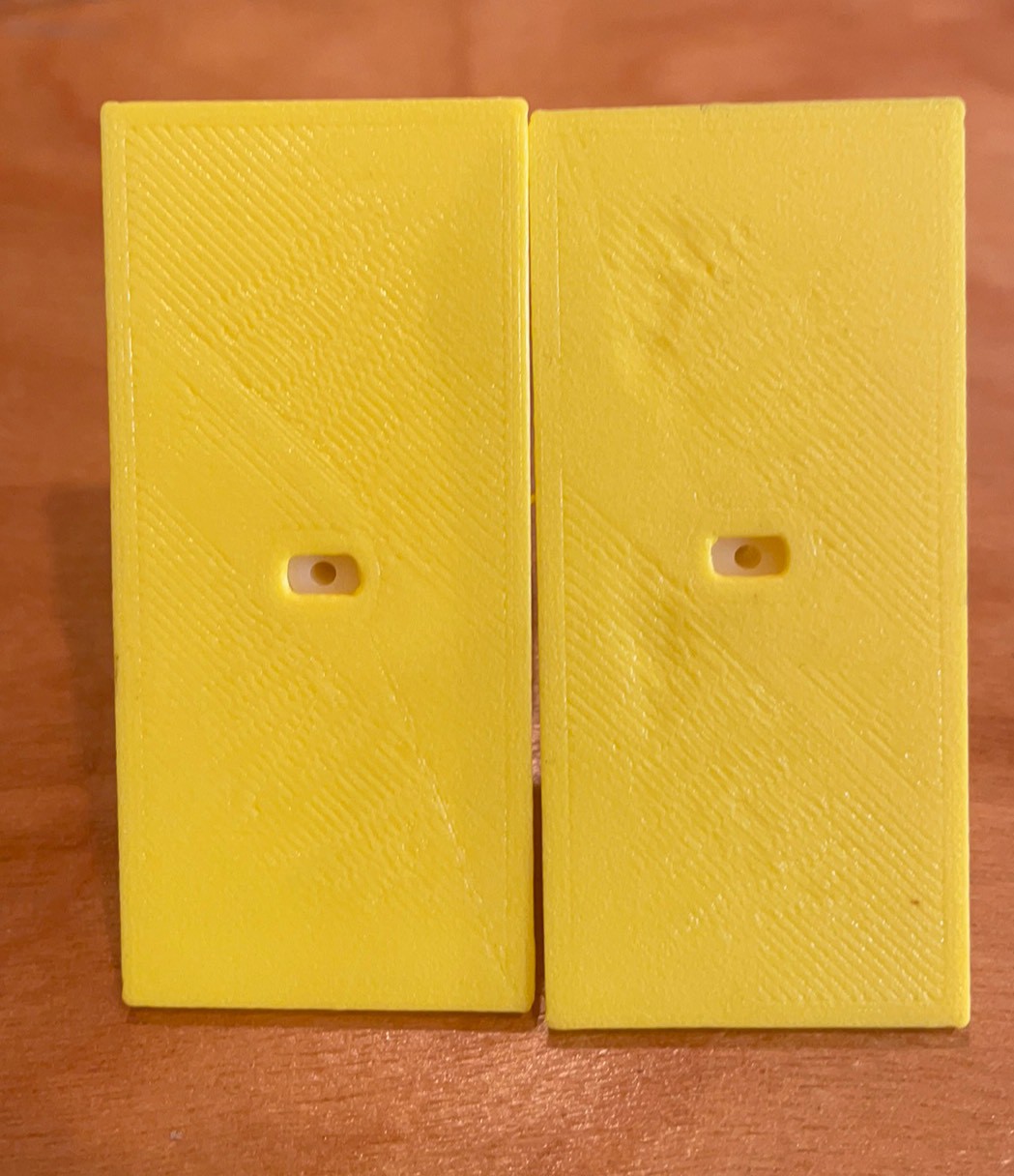
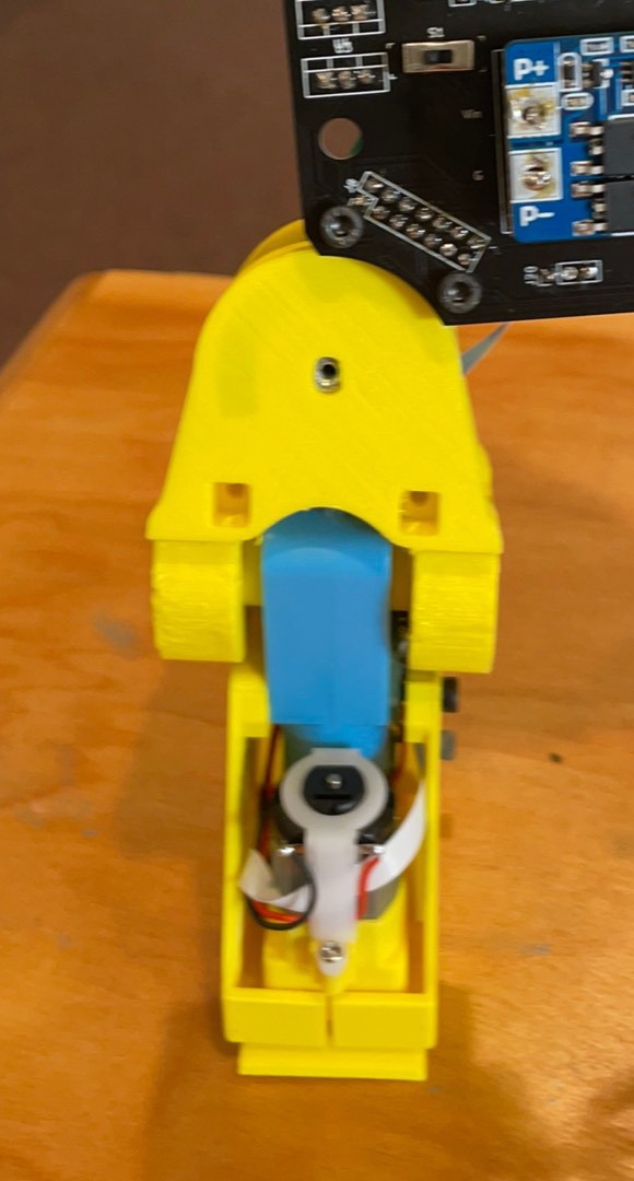
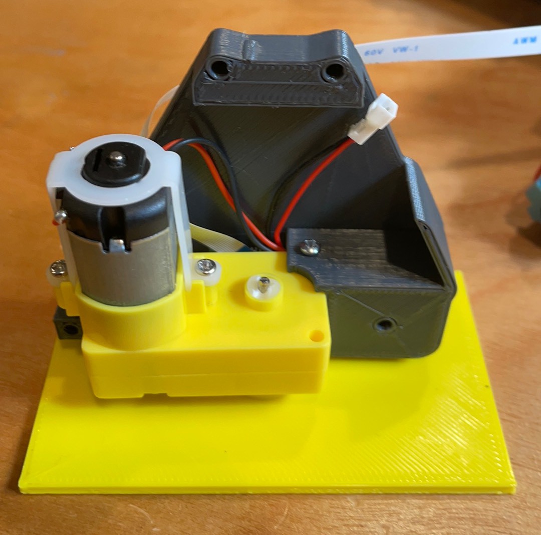
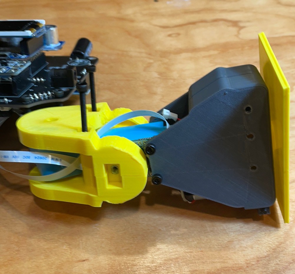
A finished foot.
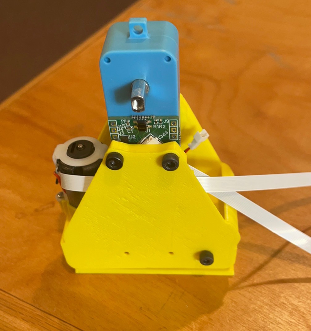
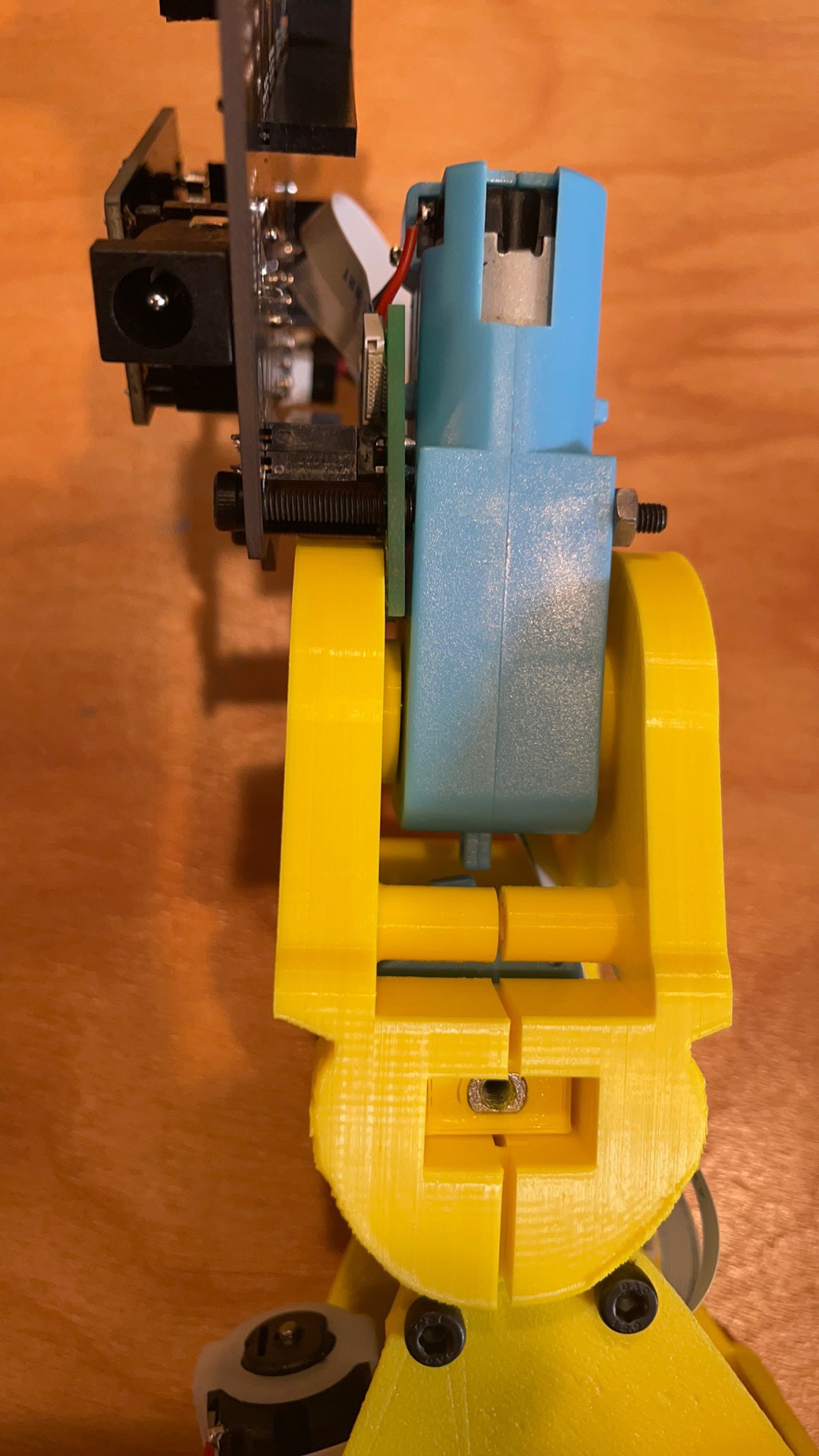
Gap at the back comes together with pressure. May need another screw boss. Not sure if the FFC against the motor will cause problems but it sure is tidy.
Need to pull the battery training wall up further. I guess it is zip ties for now.
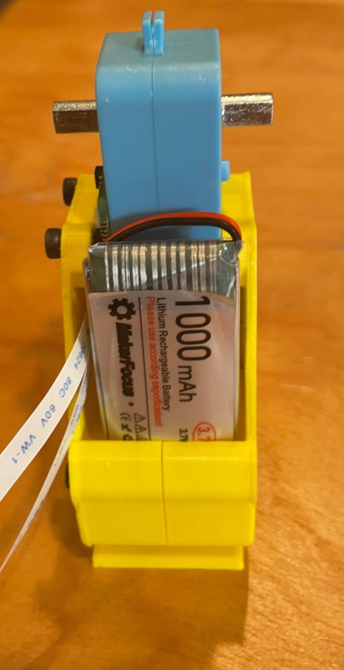
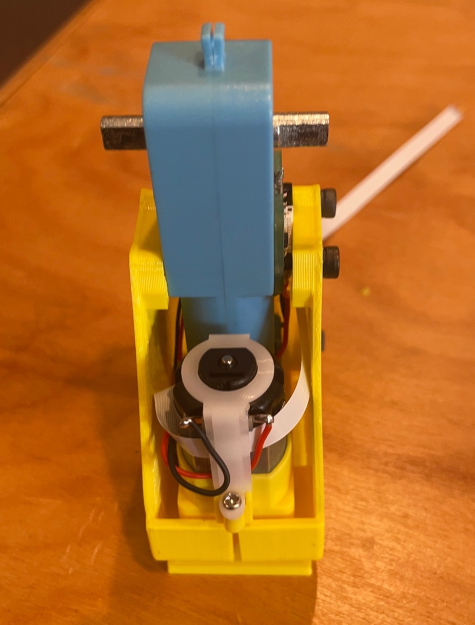
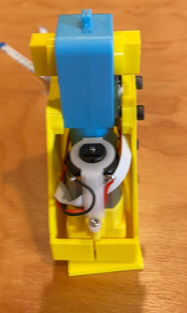
Finished. The rotation motor can slip out of its pocket. Needs a little better fixation but it functional. The 90 degrees around the shaft boss need to be opened up by 0.25 mm and a mother screw boss is needed.
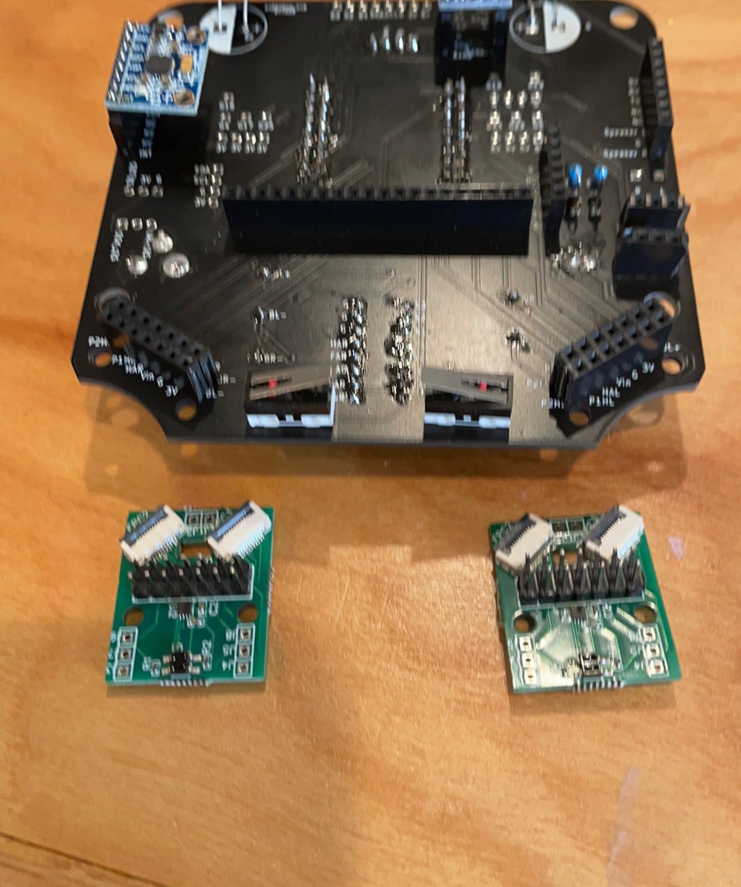
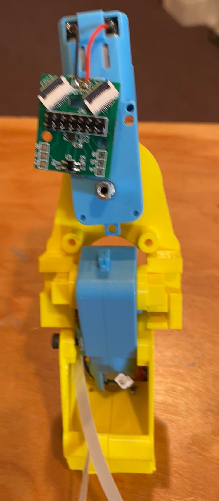
Female 2x7 headers on the back of the board and 2x7 male headers on the front of the hip boards. Be careful about the orientation because headers are hard to rework and if you can but it on backwards there is a better than even chance you will.
Three wrongs make a right? The pins need to move 2 mm down, and the rectangle window needs to be a 1mm bigger. Then if you cut way the boss it would sit flat. Now it is 2nm proud but I think it still works. Try to get it flat.
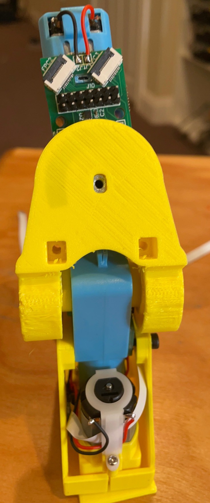
Moved it to the side with no boss and it is flat now. This keeps the motor terminals on the same side as the board which is a little cleaner.
Trimmed rectangle to height of header pins
Wires on.
Step 1 put on shaft adapters
Step 2 Hip on. Match the sensor with the slot.
Step 3 Board Forward!
Step 4 Add other hip.
Route and attach the bottom tibia or rotation FFC.
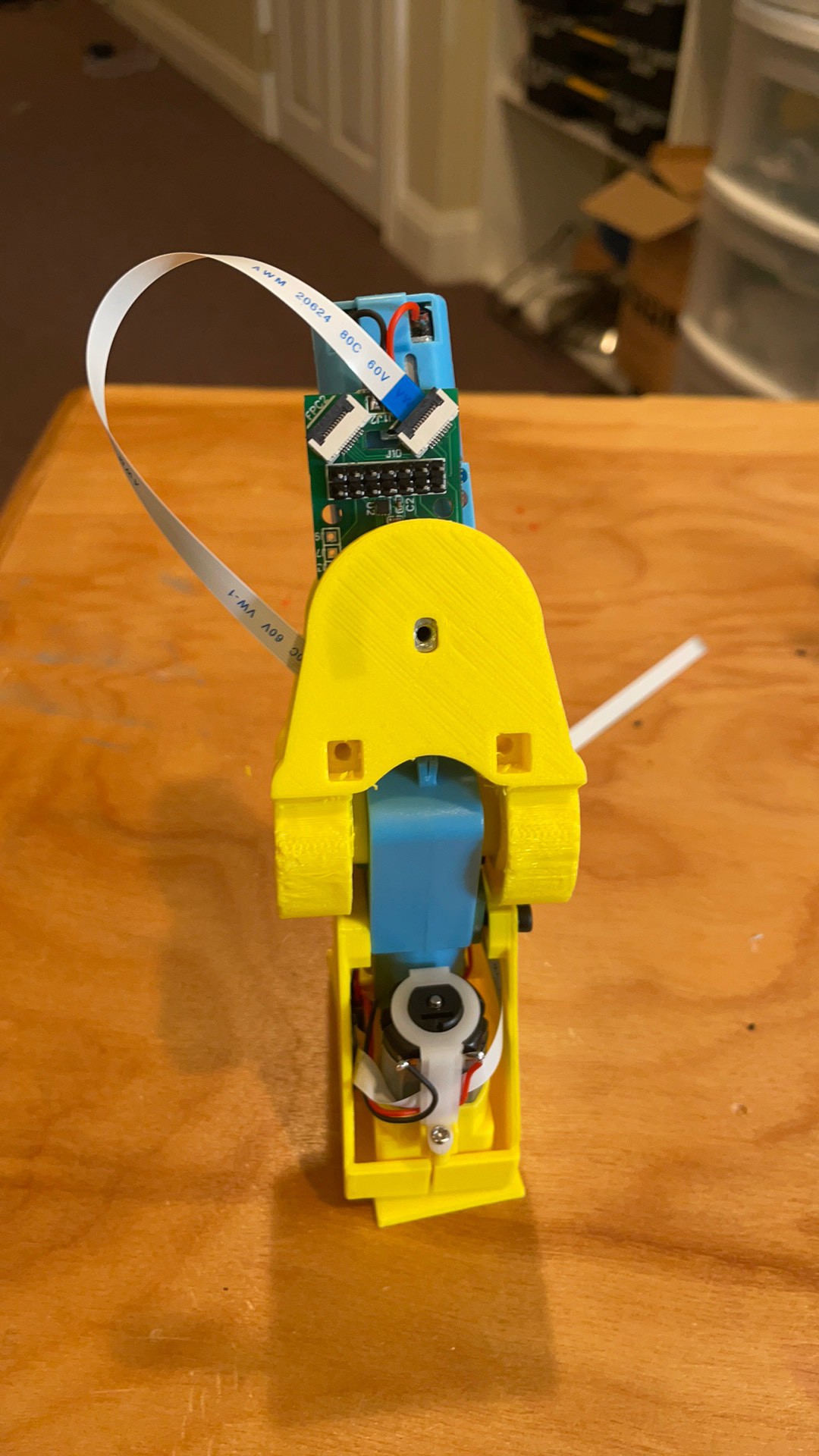
Route and attach the femur or middle motor.
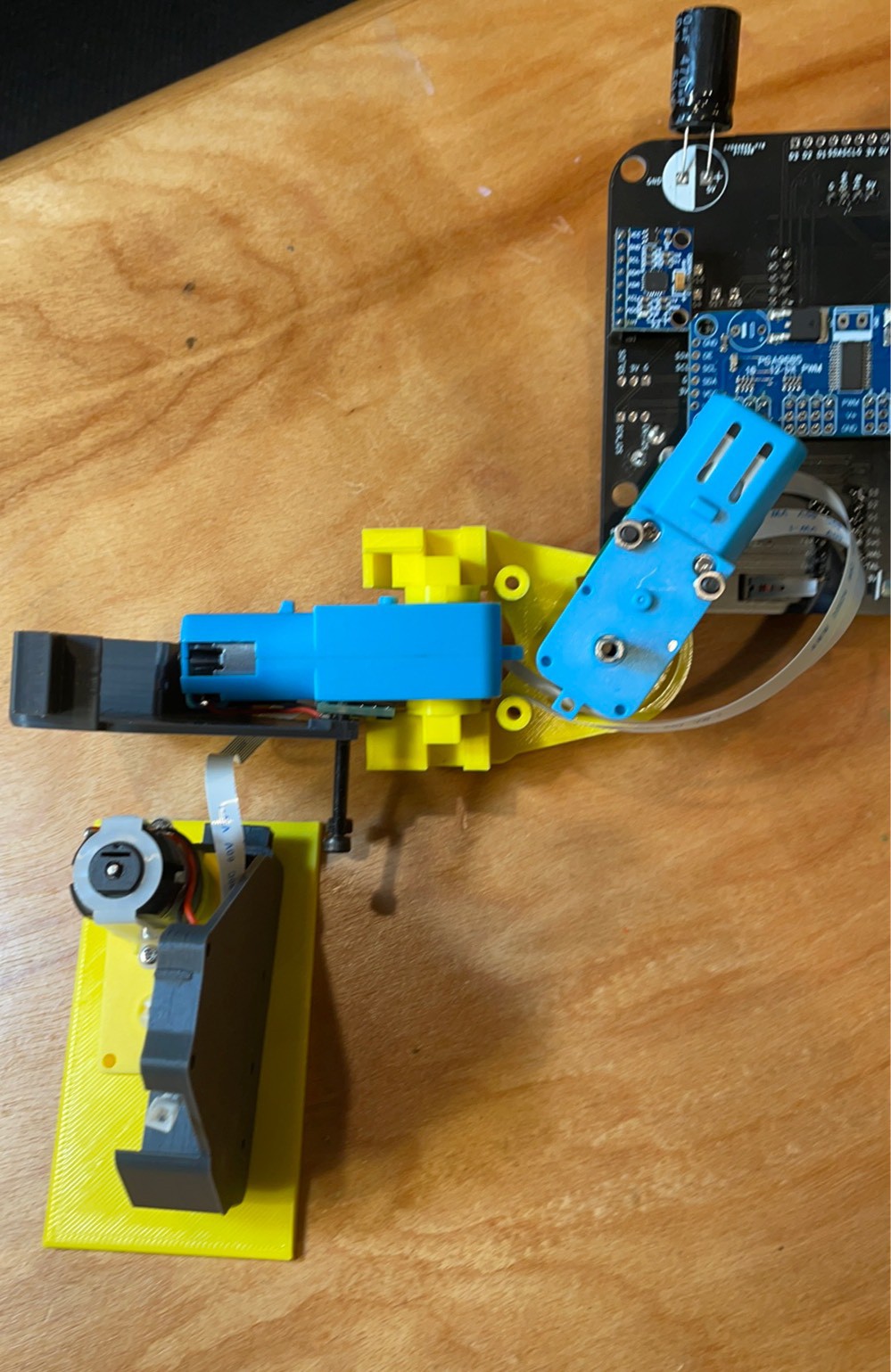
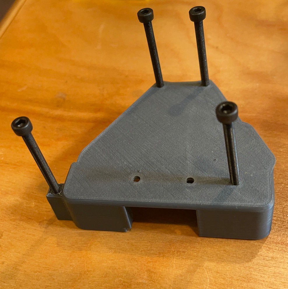
Plug one leg in and attach with 40mm m3 screws.
Which lead to backwards feet! I guess I need to turn them.
Tobi…

1 Add the Tibia board. Need to add labels to the 3D prints. Will scratch them in for now.
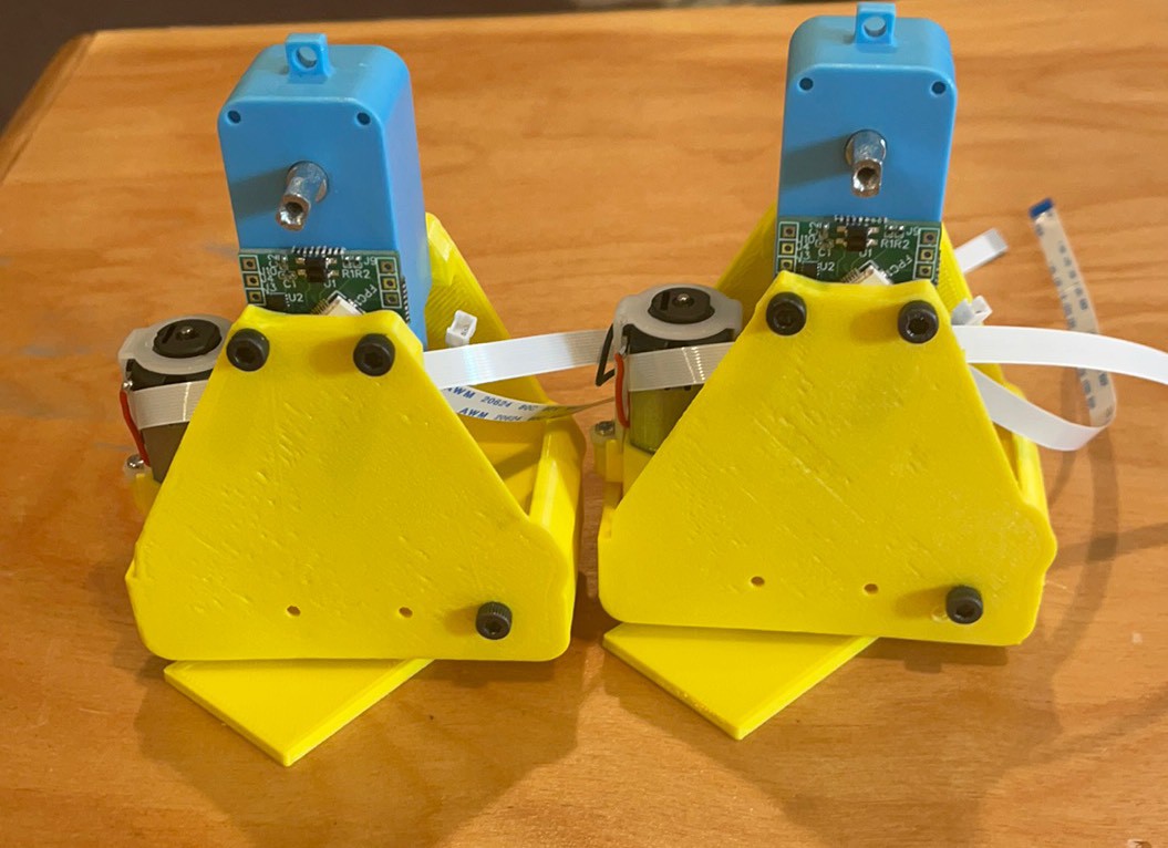
Old versus now feet. Let’s make this easy!
Attach FFC
Assemble and add 2 mm screw. I want to replace this screw but will keep it for now.
Board on femur motor facing the right way. To left when facing forward.
Add bottom screws first
Add screw at top of feet
One down. 9 screws all together. Preposition the screws when possible and save a half hour by using a cordless screwdriver.
Other foot.
Add 2 mm screw in top.
Pre-position screws on opposite side
Not quite how I planned it but it can not be changed without a reprint. Wanted the tibia motors in the back but I need to reverse the offset on the top of the ankles that makes room for the pcb to do that.

Trying again to flip the direction of the feet motors. 30 mm screws started.

Insert Tibia motor

Add 2 mm screw

Screws prostrated enough to pop into pcb holes. Deflect the plastic to do this.

Ended up putting in the screw from the pcb side because I could use the shorter 30 mm screw. Need 35 from the non pcb side.

Back to the design intent. Still can go a little higher on the batteries to hold them in better.

Discussions
Become a Hackaday.io Member
Create an account to leave a comment. Already have an account? Log In.