 Petteri Aimonen
I've finished the design for revision 4 PCBs. The schematic changes at this point are quite minimal, but it was still a complete redesign of the PCB layout.
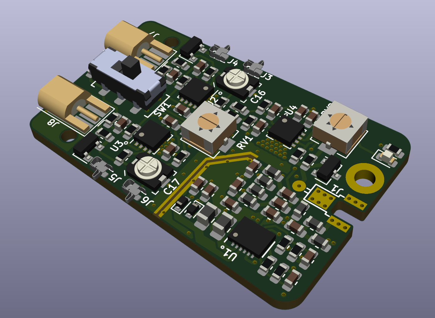
The largest change is switching to MMCX connectors for cable inputs. They appear to be better available in surface mount versions than MCX, and they are also significantly smaller. This in turn allowed placing the gain selector switch between the connectors, which made it possible to make the layout more symmetric and relocate other parts closer to the front-end amplifier. All high-speed signals now stay on top layer, which might further improve the high frequency response.
The spring contacts for the tweezer tips are now positioned at 5 mm distance instead of the previous 2 mm. This gives more leeway for inaccuracies in the plastic enclosure. The tweezer tip PCBs now have gold plated contact pads on both sides, so they can also be inserted facing outwards - this could be useful for measuring through-hole parts or some connectors.
I've switched the trimmer potentiometer to a larger and more robust Bourns 3314 type. The trimmer capacitor footprint has been modified to fit both Knowles JZ200 and JR200 types, which have lower thermal drift than the previous SGC3S300.
Revision 3 introduced a bit of resonance problem in SMPS section after I had thoughtlessly moved the ground plane under it from layer 2 to layer 3, increasing the ground plane distance from 0.2 mm to about 0.8 mm. Now the ground plane is back where it belongs and the SMPS layout has been made tighter also. I'll also switch the SMPS diodes to a lower capacitance version.
The power led is now connected to -6V rail, so it will not light if the SMPS is not operating (such as due to low voltage or over current cutoff). Because of the boost topology, +6V rail gets +5V from input even when SMPS is stopped.
Based on revision 3 tests, split ground plane for the SMPS section is beneficial in this circuit. I've however added a pair of tracks that can be soldered together to solidly connect the ground planes, so that I can better test the noise levels.
Previous versions (ab)used brass standoffs for soldering in the triax cable. That worked well, but the change to MMCX connectors moved the centerline of the board too low for that solution. Instead, a small slot is now made in the PCB edge for soldering in the triax.
Discussions
Become a Hackaday.io Member
Create an account to leave a comment. Already have an account? Log In.